Vector Mechanics for Engineers: Statics
12th Edition
ISBN: 9781259977268
Author: Ferdinand P. Beer, E. Russell Johnston Jr., David Mazurek
Publisher: McGraw-Hill Education
bartleby

Videos

Textbook Question
Book Icon
Chapter 2.2, Problem 2.36P

Knowing that the tension in cable BC is 725 N, determine the resultant of the three forces exerted at point B of beam AB.
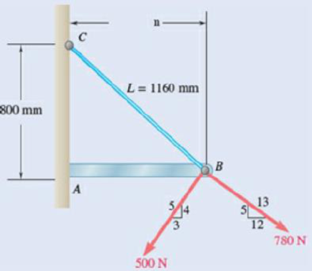
Chapter 2.2, Problem 2.36P, Knowing that the tension in cable BC is 725 N, determine the resultant of the three forces exerted

Fig. P2.36

Expert Solution & Answer
Check Mark
To determine

The resultant of the three forces shown in figure P2.36.

Answer to Problem 2.36P

The resultant of three forces shown in the figure P2.36 is 226N_.

Explanation of Solution

Figure 1 below shows the three forces acting on point A and their directions.

Vector Mechanics for Engineers: Statics, Chapter 2.2, Problem 2.36P , additional homework tip  1

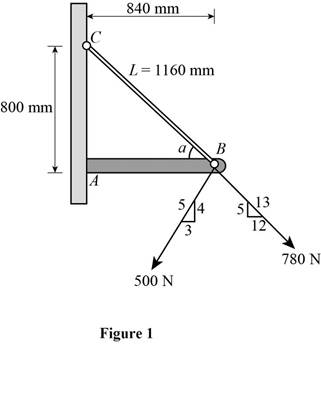
The figure shows three forces of magnitude 725N , 500N , and 780N along with their directions. Angle a is the angle between the beam AB and the wire BC.

Since these forces make an angle with the axis, they can be resolved into x and y components.

The tension in the wire BC is 725N which has a length of 1160mm. All the three forces exert its resultant force at point marked as point B in figure P2.36.

Write the equation to find the x component of 725N tension in the wire BC.

Fx1=F1cosa (I)

Here, Fx1 is the x component of 725N tension, F1 is tension due to 725N , and a is the angle between beam and direction of tension.

cos is the ratio of the adjacent side and the hypotenuse of a triangle considered in the figure.

Substitute adjacentsidehypotenuse for cosa in equation (I) to get Fx1.

Fx1=F1(adjacentsidehypotenuse) (II)

Write the equation to find the y component of the tension in the wire.

Fy1=F1sina (III)

Here, Fy1 is the y component of tension due to F1.

sina is the ratio of opposite side and the hypotenuse of the triangle considered.

Substitute oppositesidehypotenuse for sina in equation (III) to get Fy1.

Fy1=F1(oppositesidehypotenuse) (IV)

Similarly write the equation to find the x component of the 500N force along the negative x direction.

Fx2=F2cosb (V)

Here, Fx2 is the x component of 500N force , F2 is the magnitude of 500N force, and b is the angle between the 500N force vector and the beam.

cos is the ratio of the adjacent side and the hypotenuse of a triangle considered in the figure.

Substitute adjacentsidehypotenuse for cosb in equation (V) to get Fx2.

Fx2=F2cos(adjacentsidehypotenuse) (VI)

Write the equation to find the y component of 500N force along the negative y direction.

Fy2=F2sinb (VII)

Here, Fy2 is the y component of 500N force.

sinb is the ratio of opposite side and the hypotenuse of the triangle considered.

Substitute oppositesidehypotenuse for sinb in equation (VII) to get Fy2.

Fy2=F2(oppositesidehypotenuse) (VIII)

Write the equation to find the x component of the 780N force along the positive x direction.

Fx3=F3cosc (IX)

Here, Fx3 is the x component of the 780N force, F3 is the magnitude of the 780N force, c is the angle between 780N force vector and the beam.

cos is the ratio of the adjacent side and the hypotenuse of a triangle considered in the figure.

Substitute adjacentsidehypotenuse for cosc in equation (IX) to get Fx3.

Fx3=F3(adjacentsidehypotenuse) (X)

Write the equation to find the y component of 780N force along the negative y direction.

Fy3=F3sinc (XI)

Here, Fy3 is the y component of 780N force.

sinc is the ratio of opposite side and the hypotenuse of the triangle considered.

Substitute oppositesidehypotenuse for c in equation (XI) to get Fy.

Fy3=F3(oppositesidehypotenuse) (XII)

Let Rx and Ry be the x and y component of the resultant forces and R be the resultant force vector.

Write the equation to find the resultant of all the three x components.

Rx=Fx1+Fx2+Fx3=Fx (XIII)

Here, Rx is the resultant of all the three x components of force, and Fx is the sum of all the three x components of forces.

Write the equation to find the resultant of all the three y components.

Ry=Fy1+Fy2+Fy3=Fy (XIV)

Here, Fy is the sum of all the y components of three forces acting on point B.

Write the general expression of a vector with Rx and Ry as components.

R=Rxi^+Ryj^ (XV)

Express the vectors R,Rx,andRy diagrammatically as shown in figure 1. α is the angle separating the components Rx and the resultant vector R.

Vector Mechanics for Engineers: Statics, Chapter 2.2, Problem 2.36P , additional homework tip  2

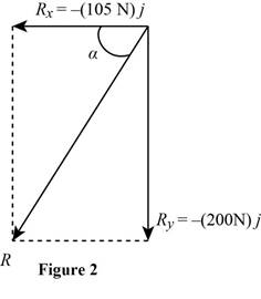
Write the equation to find the resultant of vectors Rx and Ry.

R=Rx2+Ry2 (XVI)

Here, R is the resultant force, Rx is the resultant x component of force, and Ry is the resultant of y component of force.

Write the equation to find the tangent of angle α.

tanα=RyRx (XVII)

Here, α is the angle between component Rx, and R , Ry is the y component of the resultant force, and Rx is the x component of the resultant force.

Rewrite equation (XII) to get α.

α=tan1(RyRx) (XVIII)

Conclusion:

Substitute 725N for F1, 840mm for adjacentside  and 1160mm for hypotenuse in equation (II) to get Fx1.

Fx1=(725N)840mm1160mm=525N

Substitute 725N for F1 ,800mm for oppositeside  and 1160mm for hypotenuse in equation (IV) to get Fy1.

Fy1=(725N)800mm1160mm=500N

Substitute 500N for F2 , 3mm for adjacentside and 5mm for hypotenuse in equation (VI)  to get Fx2.

Fx2=(500N)3mm5mm=300N

Substitute 500N for F2 , 5mm for hypotenuse and 4mm for oppositeside in equation (VIII) to get Fy2.

Fy2=(500N)4mm5mm=400N

Substitute 780N for F3 , 12mm for adjacentside and 13mm for hypotenuse in equation (X) to get Fx3.

Fx3=(780N)12mm13mm=720N

Substitute 780N for F3 , 5mm for oppositeside and 13mm for hypotenuse in equation (XII) to get Fy3.

Fy3=(780N)5mm13mm=300N

Substitute 525N, 300N , and 720N for Fx in equation (XIII) to get Rx

Rx=525N-300N+720N=105N

Substitute 500N , 400N , and 300N for Fy in equation (XIV) to get Ry.

Ry=500N400N300N=200N

Substitute 105N for Rx and 200N for Ry in equation (XV) to get R.

R=(105N)i^+(200N)j^

Substitute 105N for Rx and 200N for Ry in equation (XVI) to get R.

R=(105N)2+(200N)2=225.89N

Substitute 200N for Ry and 105N for Rx in equation (XIII) to get α.

α=tan1(200N105N)=62.3°

Therefore, the resultant of the three forces acting at point B shown in figure P2.36 is 226N_.

Want to see more full solutions like this?

Subscribe now to access step-by-step solutions to millions of textbook problems written by subject matter experts!
Students have asked these similar questions
A horizontal circular plate is supported by three wires at 18° angles to the vertical and attached to a support at D. Knowing that the x component of the force exerted by wire AD on the plate is 140 N, determine the magnitude of the tension in wire AD. The angle Theta is 54°.
Slider P can move along rod OA. An elastic cord PC is attached to the slider and to the vertical member BC. Knowing that the distance from O to P is 6 in. and that the tension in the cord is 3 lb, determine (a) the angle between the elastic cord and the rod OA, (b) the projection on OA of the force exerted by cord PC at point P.
The man exerts a force P of magnitude 150N on the handle of the wheelbarrow. Knowing that the resultant of the force P, Q, and W (wt of the wheelbarrow) is zero, determine W.

Chapter 2 Solutions

Vector Mechanics for Engineers: Statics

Ch. 2.1 - A steel tank is to be positioned in an excavation....Ch. 2.1 - A steel tank is to be positioned in an excavation....Ch. 2.1 - A steel tank is to be positioned in an excavation....Ch. 2.1 - For the hook support of Prob. 2.10, determine by...Ch. 2.1 - The barge B is pulled by two tugboats A and C. At...Ch. 2.1 - Solve Prob. 2.1 by trigonometry.Ch. 2.1 - Solve Prob. 2.4 by trigonometry.Ch. 2.1 - For the stake of Prob. 2.5, knowing that the...Ch. 2.1 - Two structural members A and B are bolted to a...Ch. 2.1 - Two structural members A and B are bolted to a...Ch. 2.2 - Determine the x and y components of each of the...Ch. 2.2 - Determine the x and y components of each of die...Ch. 2.2 - Determine the x and y components of each of the...Ch. 2.2 - Determine the x and y components of each of the...Ch. 2.2 - Member BC exerts on member AC a force P directed...Ch. 2.2 - Member BD exerts on member ABC a force P directed...Ch. 2.2 - The hydraulic cylinder BC exerts cm member AB a...Ch. 2.2 - Cable AC exerts on beam AD a force P directed...Ch. 2.2 - The hydraulic cylinder BD exerts on member ABC a...Ch. 2.2 - The guy wire BD exerts on the telephone pole AC a...Ch. 2.2 - Determine the resultant of the three forces of...Ch. 2.2 - Determine the resultant of the three forces of...Ch. 2.2 - Determine the resultant of the three forces of...Ch. 2.2 - Determine the resultant of the three forces of...Ch. 2.2 - Knowing that = 35, determine the resultant of the...Ch. 2.2 - Knowing that the tension in cable BC is 725 N,...Ch. 2.2 - Knowing that = 40, determine the resultant of the...Ch. 2.2 - Knowing that = 75, determine the resultant of the...Ch. 2.2 - PROBLEM 2.39 A collar that can slide on a vertical...Ch. 2.2 - Prob. 2.40PCh. 2.2 - PROBLEM 2.41 Determine (a) the required tension in...Ch. 2.2 - PROBLEM 2.42 For the block of Problems 2.37 and...Ch. 2.3 - Two cables are tied together at C and loaded as...Ch. 2.3 - Two forces of magnitude TA = 8 kips and TB = 15...Ch. 2.3 - The 60-lb collar A can slide on a frictionless...Ch. 2.3 - A chairlift has been stopped in the position...Ch. 2.3 - Two cables are tied together at C and are loaded...Ch. 2.3 - Two cables are tied together at C and are loaded...Ch. 2.3 - Two cables are tied together at C and loaded as...Ch. 2.3 - Two cables are tied together at C and are loaded...Ch. 2.3 - Two cables are tied together at C and are loaded...Ch. 2.3 - Knowing that = 20, determine the tension (a) in...Ch. 2.3 - Two cables are tied together at C and are loaded...Ch. 2.3 - Two cables are tied together at C and are loaded...Ch. 2.3 - Two forces P and Q are applied as shown to an...Ch. 2.3 - Prob. 2.52PCh. 2.3 - A welded connection is in equilibrium under the...Ch. 2.3 - A welded connection is in equilibrium under the...Ch. 2.3 - A sailor is being rescued using a boatswains chair...Ch. 2.3 - A sailor is being rescued using a boatswains chair...Ch. 2.3 - For the cables of Prob. 2.44, find the value of ...Ch. 2.3 - For the cables of Prob. 2.46, it is known that the...Ch. 2.3 - For the situation described in Fig. P2.48,...Ch. 2.3 - Two cables tied together at C are loaded as shown....Ch. 2.3 - A movable bin and its contents have a combined...Ch. 2.3 - Free-Body Diagram...Ch. 2.3 - Collar A is connected as shown to a 50-lb load and...Ch. 2.3 - Collar A is connected as shown to a 50-lb load and...Ch. 2.3 - A cable loop of length 1.5 m is placed around a...Ch. 2.3 - A 200-kg crate is to be supported by the...Ch. 2.3 - A 600-lb crate is supported by several...Ch. 2.3 - Solve parts b and d of Prob. 2.67, assuming that...Ch. 2.3 - A load Q is applied to the pulley C, which can...Ch. 2.3 - An 1800-N load Q is applied to pulley C, which can...Ch. 2.4 - Determine (a) the x, y, and z components of the...Ch. 2.4 - Determine (a) the x, y, and z components of the...Ch. 2.4 - A gun is aimed at a point A located 35 east of...Ch. 2.4 - Solve Prob. 2.73 assuming that point A is located...Ch. 2.4 - Prob. 2.75PCh. 2.4 - Prob. 2.76PCh. 2.4 - Cable AB is 65 ft long, and the tension in that...Ch. 2.4 - PROBLEM 2.78 Cable AC is 70 ft long, and the...Ch. 2.4 - Prob. 2.79PCh. 2.4 - Determine the magnitude and direction of the force...Ch. 2.4 - Prob. 2.81PCh. 2.4 - A force acts at the origin of a coordinate system...Ch. 2.4 - A force F of magnitude 210 N acts at the origin of...Ch. 2.4 - Prob. 2.84PCh. 2.4 - Two cables BG and BH are attached to frame ACD as...Ch. 2.4 - Two cables BG and BH are attached to frame ACD as...Ch. 2.4 - In order to move a wrecked truck, two cables are...Ch. 2.4 - In order to move a wrecked truck, two cables are...Ch. 2.4 - A rectangular plate is supported by three cables...Ch. 2.4 - A rectangular plate is supported by three cables...Ch. 2.4 - Find the magnitude and direction of the resultant...Ch. 2.4 - Find the magnitude and direction of the resultant...Ch. 2.4 - Knowing that the tension is 425 lb in cable AB and...Ch. 2.4 - Knowing that the tension is 510 lb in cable AB and...Ch. 2.4 - For the frame of Prob. 2.85, determine the...Ch. 2.4 - For the plate of Prob. 2.89; determine the...Ch. 2.4 - The boom OA carries a load P and is supported by...Ch. 2.4 - Prob. 2.98PCh. 2.5 - Three cables are used to tether a balloon as...Ch. 2.5 - A container of mass m = 120 kg is supported by...Ch. 2.5 - A 150-lb cylinder is supported by two cables AC...Ch. 2.5 - A transmission tower is held by three guy wires...Ch. 2.5 - A container is supported by three cables that are...Ch. 2.5 - A container is supported by three cables that are...Ch. 2.5 - Three cables are used to tether a balloon as...Ch. 2.5 - Three cables are used to tether a balloon as...Ch. 2.5 - A crate is supported by three cables as shown....Ch. 2.5 - A crate is supported by three cables as shown....Ch. 2.5 - A 12-lb circular plate of 7-in. radius is...Ch. 2.5 - Prob. 2.106PCh. 2.5 - Three cables are connected at A, where the forces...Ch. 2.5 - Fig. P2.107 and P2.108 2.108 Three cables are...Ch. 2.5 - A rectangular plate is supported by three cables...Ch. 2.5 - A rectangular plate is supported by three cables...Ch. 2.5 - A transmission tower is held by three guy wires...Ch. 2.5 - A transmission tower is held by three guy wires...Ch. 2.5 - In trying to move across a slippery icy surface, a...Ch. 2.5 - Fig. P2.113 2.114 Solve Prob. 2.113 assuming that...Ch. 2.5 - For the rectangular plate of Probs. 2.109 and...Ch. 2.5 - PROBLEM 2.116 For the cable system of Problems...Ch. 2.5 - PROBLEM 2.117 For the cable system of Problems...Ch. 2.5 - Three cables are connected at D, where an upward...Ch. 2.5 - Prob. 2.119PCh. 2.5 - Three wires are connected at point D, which is...Ch. 2.5 - A container of weight W is suspended from ring A,...Ch. 2.5 - Knowing that the tension in cable AC of the system...Ch. 2.5 - A container of weight W is suspended from ring A....Ch. 2.5 - For the system of Prob. 2.123, determine W and P...Ch. 2.5 - Fig. P2.113 2.114 Solve Prob. 2.113 assuming that...Ch. 2.5 - Prob. 2.126PCh. 2 - Two forces P and Q are applied to the lid of a...Ch. 2 - Determine the x and y components of each of the...Ch. 2 - A hoist trolley is subjected to the three forces...Ch. 2 - Knowing that = 55 and that boom AC exerts on pin...Ch. 2 - Two cables are tied together at C and loaded as...Ch. 2 - Two cables tied together at C are loaded as shown....Ch. 2 - The end of the coaxial cable AE is attached to the...Ch. 2 - Knowing that the tension in cable AC is 2130 N,...Ch. 2 - Find the magnitude and direction of the resultant...Ch. 2 - Cable BAC passes through a frictionless ring A and...Ch. 2 - Collars A and B are connected by a 25-in.-lang...Ch. 2 - Fig. P2.137 and P2.138 2.138 Collars A and B are...
Knowledge Booster
Background pattern image
Mechanical Engineering
Learn more about
Need a deep-dive on the concept behind this application? Look no further. Learn more about this topic, mechanical-engineering and related others by exploring similar questions and additional content below.
Similar questions
SEE MORE QUESTIONS
Recommended textbooks for you
Text book image
Elements Of Electromagnetics
Mechanical Engineering
ISBN:9780190698614
Author:Sadiku, Matthew N. O.
Publisher:Oxford University Press
Text book image
Mechanics of Materials (10th Edition)
Mechanical Engineering
ISBN:9780134319650
Author:Russell C. Hibbeler
Publisher:PEARSON
Text book image
Thermodynamics: An Engineering Approach
Mechanical Engineering
ISBN:9781259822674
Author:Yunus A. Cengel Dr., Michael A. Boles
Publisher:McGraw-Hill Education
Text book image
Control Systems Engineering
Mechanical Engineering
ISBN:9781118170519
Author:Norman S. Nise
Publisher:WILEY
Text book image
Mechanics of Materials (MindTap Course List)
Mechanical Engineering
ISBN:9781337093347
Author:Barry J. Goodno, James M. Gere
Publisher:Cengage Learning
Text book image
Engineering Mechanics: Statics
Mechanical Engineering
ISBN:9781118807330
Author:James L. Meriam, L. G. Kraige, J. N. Bolton
Publisher:WILEY
How to balance a see saw using moments example problem; Author: Engineer4Free;https://www.youtube.com/watch?v=d7tX37j-iHU;License: Standard Youtube License