
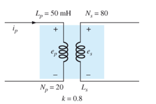
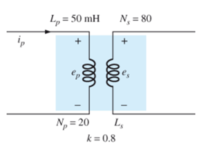
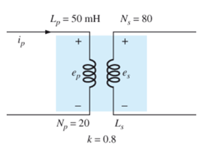
For the air-core transformer in Fig. 23.57:
- Find the value of Ls, if the mutual inductance M is equal to 40 mH.
- Find the induced voltages
- and
- if the flux linking the primary coil changes at the rate of 0.08 Wb/s.
- Find the induced voltages
- changes at the rate of 0.3 A/ms.
(a)
Value of
Answer to Problem 1P
Value of
Explanation of Solution
Given:
Mutual inductance, M = 40mH
Formula used:
Value of
Calculation:
With the known values, value of
We know that
Conclusion:
Thus, the value of
(b)
The value of the primary and secondary induced voltage at the rate of
Answer to Problem 1P
The value of primary induced voltage is 1.6V
The value of secondary induced voltage is 5.12V
Explanation of Solution
Given:
Formula used:
The primary induced voltage is calculated by
The secondary induced voltage is calculated by
Calculation:
With the known values, the primary induced voltage is calculated as
Substitute
The value of primary induced voltage is 1.6V
Secondary induced voltage,
Substitute
The value of secondary induced voltage is 5.12V
Conclusion:
Thus, the value of primary induced voltage is 1.6V and the value of secondary induced voltage is 5.12V
(c)
The value of the primary and secondary induced voltage at the rate of
Answer to Problem 1P
Value of primary induced voltage is 15V
Value of secondary induced voltage is 12V
Explanation of Solution
Given:
Formula used:
Primary induced voltage is calculated by
The secondary induced voltage is calculated by
Calculation:
With the known values, the primary induced voltage is calculated as
Substitute
Thus, the primary induced voltage is 15V
The secondary induced voltage is
Substitute
The secondary induced voltage is 12V
Conclusion:
Thus, the value of primary induced voltage is 15V and the value of secondary induced voltage is 12V
Want to see more full solutions like this?
Chapter 23 Solutions
Introductory Circuit Analysis (13th Edition)
Additional Engineering Textbook Solutions
ELECTRICITY FOR TRADES (LOOSELEAF)
ANALYSIS+DESIGN OF LINEAR CIRCUITS(LL)
Electric Circuits (10th Edition)
Electronics Fundamentals: Circuits, Devices & Applications
Programmable Logic Controllers
Loose Leaf for Engineering Circuit Analysis Format: Loose-leaf

- Given: HW Rectifier; transformer secondary voltage=32V; Capacitance 4700 micro farads; average load voltage is 18V. Determine the ripple factor and average load current.arrow_forwardQ25. The function of the iron core in the transformer isarrow_forwardQ25/ (b) A transformer takes a current of 0.8A, when its primary is connected to a 215V, 50Hz supply, the secondary being open circuited. If the power absorbed is 65watts, determine (i) the core loss current(Ic) (ii) the power factor on no-load and (iii) the magnetizing current(Im)arrow_forward
- Q4: A 50 Hz, 11KV, 3-ph, alternator with earthed neutral has a reactance of 5 Ω\ ph and is connected to bus bar through a C.B. The distributed capacitance up to C.B between phase and neutral is 0.01μF, determine: 1-the recovery voltage across the contacts of the breaker, 2-the frequency of oscillation, 3- The restriking voltage across the contacts of the breaker, 4-the average rate of rise of restriking voltage up to the first peak, 5- the time to reach the peak restriking voltage, 6- the value of resistance to be used across the contacts of C.B. to eliminate the restriking voltage, and 7- the value of inductance and capacitance of this systemarrow_forwardWhen one coil of magnetically coupled pair has a current of 5 Amp, the resulting flux Φ11 = 0.4 mWb and flux Φ12 = 0.8 mWb respectively. If the turns are N1 = 500 and N2 = 1500, Find L1 and coupling coefficient k.arrow_forward6. A generator delivers power through a transmission line at 23 kV. The resulting line loss across the 23-kV transmission line is 7.6 MW. To reduce the losses, a step-up transformer rated 23 KV/230 kV is used. What will be the new loss in MW across a 230-kV transmission line? (four decimal places)arrow_forward
- Calculate Required size of core and calculate number of turns in primary and secondary for small transformer whose, Output (secondary) voltage (Vs or Vo)= 12. V Output (secondary) current Io = 3 A Primary voltage, Vp = 230 V Supply frequency, f- 50 Hz Assume efficiency, 90%arrow_forwardA 250 kVA, 11 000 V/400 V, 50 Hz single-phase transformer has 80 turns on the secondary. Calculate:(a) the approximate values of the primary and secondary currents;(b) the approximate number of primary turns; (c) the maximum value of the flux. (d) the frequency of secondary.arrow_forwardA 20 kVA closet transformer located inside a building is used to step down thevoltage for the building. It is connected to a primary 4800 V AC power source.The ratio of the number of primary windings to the number of secondarywindings on the transformer is 20 to 40. determine a) voltage provided to the building b) amount of current provided to the building c) if building consumes 3200W of power what is its power factor d) phase angle of the secondary source in the buildingarrow_forward
- Q23. If DC voltage of 240 V is connected to the primary of a transformer having 1:10 turns ratio, then the voltage across the secondary winding will be.arrow_forwardA 246 kVA transformer has a primary winding resistance of 0.55 and a secondary winding resistance of 0.002 Q. The iron loss is 3 kW and the primary and secondary voltages are 4 kV and 245 V respectively. If the power factor of the load is 0.85,then determine the efficiency of the transformer on 25 % load.arrow_forwardA. What are the various causes of voltage drop in atransformer? B. A single phase transformer has arated secondary voltage of (230v).when Loaded by a purely inductive load to its rated Value of current ,its terminal voltage drops to (200 v). Calculate its regulation and efficiency.arrow_forward
 Introductory Circuit Analysis (13th Edition)Electrical EngineeringISBN:9780133923605Author:Robert L. BoylestadPublisher:PEARSON
 Delmar's Standard Textbook Of ElectricityElectrical EngineeringISBN:9781337900348Author:Stephen L. HermanPublisher:Cengage Learning
 Programmable Logic ControllersElectrical EngineeringISBN:9780073373843Author:Frank D. PetruzellaPublisher:McGraw-Hill Education
 Fundamentals of Electric CircuitsElectrical EngineeringISBN:9780078028229Author:Charles K Alexander, Matthew SadikuPublisher:McGraw-Hill Education
 Electric Circuits. (11th Edition)Electrical EngineeringISBN:9780134746968Author:James W. Nilsson, Susan RiedelPublisher:PEARSON
 Engineering ElectromagneticsElectrical EngineeringISBN:9780078028151Author:Hayt, William H. (william Hart), Jr, BUCK, John A.Publisher:Mcgraw-hill Education,