
Videos
Determine the following for the pulse waveforms of Fig. 25.51:
a. whether it is positive-or negative-going
b. base-line voltage
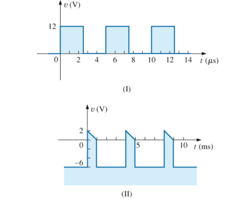
c. pulse width
d. amplitude
e. % tilt
(a)
Whether the waveform is positive going or negative going.
Answer to Problem 1P
The pulse waveform is positive going for case 1 and pulse waveform is positive going for case 2.
Explanation of Solution
Calculation:
Case 1:
Pulse waveform increases in positive direction from the base line therefore it is positive going pulse waveform.
Case 2:
Pulse waveform increases in positive direction from the base line therefore it is positive going pulse waveform.
Conclusion:
Thus, pulse waveform is positive going for case 1 and pulse waveform is positive going for case 2.
(b)
The value of base line voltage.
Answer to Problem 1P
The base line voltage is
Explanation of Solution
Concept used:
Base line voltage is the value of starting point voltage for pulse waveform.
Calculation:
Case 1:
In the waveform starting value of voltage is
Case 2:
In the waveform starting value of voltage is
Conclusion:
Thus, base line voltage is
(c)
The value of pulse width.
Answer to Problem 1P
The value of pulse width is
Explanation of Solution
Concept used:
Write the expression for pulse width.
Here,
Calculation:
Case 1:
Substitute
Therefore, value of pulse width is
Case 2:
Substitute
Therefore, value of pulse width is
Conclusion:
Thus ,value of pulse width is
(d)
The value of amplitude.
Answer to Problem 1P
The value of amplitude is
Explanation of Solution
Concept used:
Write the expression for peak to peak value.
Here,
Calculation:
Amplitude of pulse waveform is equal to peak to peak value of the waveform.
Case 1:
Substitute
The value of amplitude is
Case 2:
Substitute
The value of amplitude is
Conclusion:
Thus, value of amplitude is
(e)
The
Answer to Problem 1P
The
Explanation of Solution
Concept used:
Write the expression for
Here,
Calculation:
Case 1:
Substitute
Case 2:
Substitute
Conclusion:
Thus, the
Want to see more full solutions like this?
Chapter 25 Solutions
EBK INTRODUCTORY CIRCUIT ANALYSIS
Additional Engineering Textbook Solutions
Fundamentals of Electric Circuits
Electrical Engineering: Principles & Applications (7th Edition)
Loose Leaf for Engineering Circuit Analysis Format: Loose-leaf
Electric machinery fundamentals
ANALYSIS+DESIGN OF LINEAR CIRCUITS(LL)
Microelectronics: Circuit Analysis and Design


- q27arrow_forwardThe period of this signal is about------ ms (milliseconds). The oscilloscope range selector determines the scale on the screen. That means number of volts per line for amplitude vertical (v/div) and the number of milliseconds per line for time horizontally (ms/div).arrow_forwardAn AM mobile transmitter supplies 8 kW of carrier power to a 42 Ohms load. The carrier signal is modulated by a 4 kHz sine wave to a depth of 46 % at a frequency of 15 MHz. The peak voltage of the modulating signal is __ V.arrow_forward
- An AM transmitter at 27 MHz develops 10W of carrier power into a 50-ohm load. It is modulated by 2-kHz sine wave between 20% and 90% modulation. Determine maximum and minimum waveform voltage of the AM signal at 20%. Ans: Vmax=37.94V and Vmin=25.3Varrow_forwardDraw the electrical model of a piezoelectric crystal. (ii) Over what portion of the reactance curve do we desire oscillations to take place when the crystal is used as part of a sinusoidal oscillator? Explain.arrow_forwardassume f=60Hzarrow_forward
 Introductory Circuit Analysis (13th Edition)Electrical EngineeringISBN:9780133923605Author:Robert L. BoylestadPublisher:PEARSON
 Delmar's Standard Textbook Of ElectricityElectrical EngineeringISBN:9781337900348Author:Stephen L. HermanPublisher:Cengage Learning
 Programmable Logic ControllersElectrical EngineeringISBN:9780073373843Author:Frank D. PetruzellaPublisher:McGraw-Hill Education
 Fundamentals of Electric CircuitsElectrical EngineeringISBN:9780078028229Author:Charles K Alexander, Matthew SadikuPublisher:McGraw-Hill Education
 Electric Circuits. (11th Edition)Electrical EngineeringISBN:9780134746968Author:James W. Nilsson, Susan RiedelPublisher:PEARSON
 Engineering ElectromagneticsElectrical EngineeringISBN:9780078028151Author:Hayt, William H. (william Hart), Jr, BUCK, John A.Publisher:Mcgraw-hill Education,