
Physics for Scientists and Engineers, Technology Update (No access codes included)
9th Edition
ISBN: 9781305116399
Author: Raymond A. Serway, John W. Jewett
Publisher: Cengage Learning
expand_more
expand_more
format_list_bulleted
Videos
Textbook Question
Chapter 26, Problem 26.24P
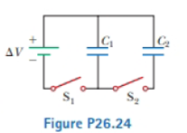
Consider the circuit shown in Figure P26.24, where C1, = 6.00 µF, C2 = 3.00 µF. and ΔV = 20.0 V. Capacitor C1 is first charged by closing switch S1. Switch S1 is then opened, and the charged capacitor is connected to the uncharged capacitor by closing Calculate (a) the initial charge acquired by C, and (b) the final charge on each capacitor.
Expert Solution & Answer

Trending nowThis is a popular solution!

Chapter 26 Solutions
Physics for Scientists and Engineers, Technology Update (No access codes included)
Ch. 26 - A capacitor stores charge Q at a potential...Ch. 26 - Many computer keyboard buttons are constructed of...Ch. 26 - Two capacitors are identical. They can be...Ch. 26 - You have three capacitors and a battery. In which...Ch. 26 - If you have ever tried to hang a picture or a...Ch. 26 - A fully charged parallel-plate capacitor remains...Ch. 26 - By what factor is the capacitance of a metal...Ch. 26 - An electronics technician wishes to construct a...Ch. 26 - A parallel-plate capacitor is connected to a...Ch. 26 - If three unequal capacitors, initially uncharged,...
Ch. 26 - Assume a device is designed to obtain a large...Ch. 26 - (i) What happens to the magnitude of the charge...Ch. 26 - A capacitor with very large capacitance is in...Ch. 26 - A parallel-plate capacitor filled with air carries...Ch. 26 - (i) A battery is attached to several different...Ch. 26 - A parallel-plate capacitor is charged and then is...Ch. 26 - (i) Rank the following five capacitors from...Ch. 26 - True or False? (a) From the definition of...Ch. 26 - You charge a parallel-plate capacitor, remove it...Ch. 26 - (a) Why is it dangerous to touch the terminals of...Ch. 26 - Assume you want to increase the maximum operating...Ch. 26 - If you were asked to design a capacitor in which...Ch. 26 - Prob. 26.4CQCh. 26 - Explain why the work needed to move a particle...Ch. 26 - An air-filled capacitor is charged, then...Ch. 26 - The sum of the charges on both plates of a...Ch. 26 - Because the charges on the plates of a...Ch. 26 - (a) When a battery is connected to the plates of a...Ch. 26 - Two conductors having net charges of +10.0 C and...Ch. 26 - (a) How much charge is on each plate of a 4.00-F...Ch. 26 - An air-filled parallel-plate capacitor has plates...Ch. 26 - A 50.0-in length of coaxial cable has an inner...Ch. 26 - (a) Regarding (lie Earth and a cloud layer 800 m...Ch. 26 - When a potential difference of 150 V is applied to...Ch. 26 - Prob. 26.8PCh. 26 - An air-filled capacitor consists of two parallel...Ch. 26 - A variable air capacitor used in a radio tuning...Ch. 26 - An isolated, charged conducting sphere of radius...Ch. 26 - Review. A small object of mass m carries a charge...Ch. 26 - Two capacitors, C1 = 5.00 F and C2 = 12.0 F, are...Ch. 26 - What If? The two capacitors of Problem 13 (C1 =...Ch. 26 - Find the equivalent capacitance of a 4.20-F...Ch. 26 - Prob. 26.16PCh. 26 - According to its design specification, the timer...Ch. 26 - Why is the following situation impossible? A...Ch. 26 - For the system of four capacitors shown in Figure...Ch. 26 - Three capacitors are connected to a battery as...Ch. 26 - A group of identical capacitors is connected first...Ch. 26 - (a) Find the equivalent capacitance between points...Ch. 26 - Four capacitors are connected as shown in Figure...Ch. 26 - Consider the circuit shown in Figure P26.24, where...Ch. 26 - Find the equivalent capacitance between points a...Ch. 26 - Find (a) the equivalent capacitance of the...Ch. 26 - Two capacitors give an equivalent capacitance of...Ch. 26 - Two capacitors give an equivalent capacitance of...Ch. 26 - Consider three capacitors C1, C2. and C3 and a...Ch. 26 - The immediate cause of many deaths is ventricular...Ch. 26 - A 12.0-V battery is connected to a capacitor,...Ch. 26 - A 3.00-F capacitor is connected to a 12.0-V...Ch. 26 - As a person moves about in a dry environment,...Ch. 26 - Two capacitors, C1 = 18.0 F and C2 = 36.0 F, are...Ch. 26 - Two identical parallel-plate capacitors, each with...Ch. 26 - Two identical parallel-plate capacitors, each with...Ch. 26 - Two capacitors, C1 = 25.0 F and C2 = 5.00 F, are...Ch. 26 - A parallel-plate capacitor has a charge Q and...Ch. 26 - Review. A storm cloud and the ground represent the...Ch. 26 - Consider two conducting spheres with radii R1 and...Ch. 26 - Review. The circuit in Figure P26.41 (page 804)...Ch. 26 - A supermarket sells rolls of aluminum foil,...Ch. 26 - (a) How much charge can be placed 011 a capacitor...Ch. 26 - The voltage across an air-filled parallel-plate...Ch. 26 - Determine (a) the capacitance and (b) the maximum...Ch. 26 - A commercial capacitor is to be constructed as...Ch. 26 - A parallel-plate capacitor in air has a plate...Ch. 26 - Each capacitor in the combination shown in Figure...Ch. 26 - A 2.00-nF parallel-plate capacitor is charged to...Ch. 26 - A small rigid object carries positive and negative...Ch. 26 - An infinite line of positive charge lies along the...Ch. 26 - A small object with electric dipole moment p is...Ch. 26 - The general form of Gausss law describes how a...Ch. 26 - Find the equivalent capacitance of' the group of...Ch. 26 - Four parallel metal plates P1, P2, P3, and P4,...Ch. 26 - For (he system of four capacitors shown in Figure...Ch. 26 - A uniform electric field E = 3 000 V/m exists...Ch. 26 - Two large, parallel metal plates, each of area A,...Ch. 26 - A parallel-plate capacitor is constructed using a...Ch. 26 - Why is the following situation impossible? A...Ch. 26 - Prob. 26.61APCh. 26 - A parallel-plate capacitor with vacuum between its...Ch. 26 - A 10.0-F capacitor is charged to 15.0 V. It is...Ch. 26 - Assume that the internal diameter of the...Ch. 26 - Two square plates of sides are placed parallel to...Ch. 26 - (a) Two spheres have radii a and b, and their...Ch. 26 - A capacitor of unknown capacitance has been...Ch. 26 - A parallel-plate capacitor of plate separation d...Ch. 26 - Prob. 26.69APCh. 26 - Example 25.1 explored a cylindrical capacitor of...Ch. 26 - To repair a power supply for a stereo amplifier,...Ch. 26 - The inner conductor of a coaxial cable has a...Ch. 26 - Some physical systems possessing capacitance...Ch. 26 - Consider two long, parallel, and oppositely...Ch. 26 - Determine the equivalent capacitance of the...Ch. 26 - A parallel-plate capacitor with plates of area LW...Ch. 26 - Calculate the equivalent capacitance between...Ch. 26 - A capacitor is constructed from two square,...
Knowledge Booster


Learn more about
Need a deep-dive on the concept behind this application? Look no further. Learn more about this topic, physics and related others by exploring similar questions and additional content below.Similar questions
- Consider the circuit shown in Figure P20.52, where C1 = 6.00 F, C2 = 3.00 F, and V = 20.0 V. Capacitor C1 is first charged by closing switch S1. Switch S1 is then opened, and the charged capacitor is connected to the uncharged capacitor by closing S2. Calculate (a) the initial charge acquired by C1 and (b) the final charge on each capacitor. Figure P20.52arrow_forwardA charge Q is placed on a capacitor of capacitance C. The capacitor is connected into the circuit shown in Figure P26.37, with an open switch, a resistor, and an initially uncharged capacitor of capacitance 3C. The switch is then closed, and the circuit comes to equilibrium. In terms of Q and C, find (a) the final potential difference between the plates of each capacitor, (b) the charge on each capacitor, and (c) the final energy stored in each capacitor. (d) Find the internal energy appearing in the resistor. Figure P26.37arrow_forwardA battery is used to charge a capacitor through a resistor as shown in Figure P27.44. Show that half the energy supplied by the battery appears as internal energy in the resistor and half is stored in the capacitor. Figure P27.44arrow_forward
- A Pairs of parallel wires or coaxial cables are two conductors separated by an insulator, so they have a capacitance. For a given cable, the capacitance is independent of the length if the cable is very long. A typical circuit model of a cable is shown in Figure P27.87. It is called a lumped-parameter model and represents how a unit length of the cable behaves. Find the equivalent capacitance of a. one unit length (Fig. P27.87A), b. two unit lengths (Fig. P27.87B), and c. an infinite number of unit lengths (Fig. P27.87C). Hint: For the infinite number of units, adding one more unit at the beginning does not change the equivalent capacitance.arrow_forwardThe circuit in Figure P21.59 has been connected for a long time. (a) What is the potential difference across the capacitor? (b) If the battery is disconnected from the circuit, over what time interval does the capacitor discharge to one-tenth its initial voltage?arrow_forwardThe circuit in Figure P27.85 shows four capacitors connected to a battery. The switch S is initially open, and all capacitors have reached their final charge. The capacitances are C1 = 6.00 F, C2 = 12.00 F, C3 = 8.00 F, and C4 = 4.00 F. a. Find the potential difference across each capacitor and the charge stored in each. b. The switch is now closed. What is the new final potential difference across each capacitor and the new charge stored in each? Figure P27.85arrow_forward
- The circuit shown in Figure P28.78 is set up in the laboratory to measure an unknown capacitance C in series with a resistance R = 10.0 M powered by a battery whose emf is 6.19 V. The data given in the table are the measured voltages across the capacitor as a function of lime, where t = 0 represents the instant at which the switch is thrown to position b. (a) Construct a graph of In (/v) versus I and perform a linear least-squares fit to the data, (b) From the slope of your graph, obtain a value for the time constant of the circuit and a value for the capacitance. v(V) t(s) In (/v) 6.19 0 5.56 4.87 4.93 11.1 4.34 19.4 3.72 30.8 3.09 46.6 2.47 67.3 1.83 102.2arrow_forwardDraw two graphs of charge versus time on a capacitor. Draw one for charging an initially uncharged capacitor in series with a resistor, as in the circuit in Figure 21.38, starting from t = 0. Draw the other for discharging a capacitor through a resistor, as in the circuit in Figure 21.39, starting at t = 0, with an initial charge Q0. Show at least two intervals of t.arrow_forwardA capacitor with initial charge Q0 is connected across a resistor R at time t = 0. The separation between the plates of the capacitor changes as d = d0/(1 + t) for 0 t 1 s. Find an expression for the voltage drop across the capacitor as a function of time.arrow_forward
- Assume a length of axon membrane of about 0.10 m is excited by an action potential (length excited = nerve speed pulse duration = 50.0 m/s 2.0 103 s = 0.10 m). In the resting state, the outer surface of the axon wall is charged positively with K+ ions and the inner wall has an equal and opposite charge of negative organic ions, as shown in Figure P18.43. Model the axon as a parallel-plate capacitor and take C = 0A/d and Q = C V to investigate the charge as follows. Use typical values for a cylindrical axon of cell wall thickness d = 1.0 108 m, axon radius r = 1.0 101 m, and cell-wall dielectric constant = 3.0. (a) Calculate the positive charge on the outside of a 0.10-m piece of axon when it is not conducting an electric pulse. How many K+ ions are on the outside of the axon assuming an initial potential difference of 7.0 102 V? Is this a large charge per unit area? Hint: Calculate the charge per unit area in terms of electronic charge e per squared (2). An atom has a cross section of about 1 2 (1 = 1010 m). (b) How much positive charge must flow through the cell membrane to reach the excited state of + 3.0 102 V from the resting state of 7.0 102 V? How many sodium ions (Na+) is this? (c) If it takes 2.0 ms for the Na+ ions to enter the axon, what is the average current in the axon wall in this process? (d) How much energy does it take to raise the potential of the inner axon wall to + 3.0 102 V, starting from the resting potential of 7.0 102 V? Figure P18.43 Problem 43 and 44.arrow_forwardIf the terminals of a battery with zero internal resistance are connected across two identical resistors in series, the total power delivered by the battery is 8.00 W. If the same battery is connected across the same resistors in parallel, what is the total power delivered by the battery? (a) 16.0 W (b) 32.0 W (c) 2.00 W (d) 4.00 W (e) none of those answersarrow_forwardIn Figure P29.81, N real batteries, each with an emf and internal resistance r, are connected in a closed ring. A resistor R can be connected across any two points of this ring, causing there to be n real batteries in one branch and N n resistors in the other branch. Find an expression for the current through the resistor R in this case.arrow_forward
arrow_back_ios
SEE MORE QUESTIONS
arrow_forward_ios
Recommended textbooks for you
 Physics for Scientists and Engineers, Technology ...PhysicsISBN:9781305116399Author:Raymond A. Serway, John W. JewettPublisher:Cengage Learning
 Principles of Physics: A Calculus-Based TextPhysicsISBN:9781133104261Author:Raymond A. Serway, John W. JewettPublisher:Cengage Learning
 College PhysicsPhysicsISBN:9781285737027Author:Raymond A. Serway, Chris VuillePublisher:Cengage Learning
 College PhysicsPhysicsISBN:9781305952300Author:Raymond A. Serway, Chris VuillePublisher:Cengage Learning
 Physics for Scientists and Engineers: Foundations...PhysicsISBN:9781133939146Author:Katz, Debora M.Publisher:Cengage Learning
 Physics for Scientists and Engineers with Modern ...PhysicsISBN:9781337553292Author:Raymond A. Serway, John W. JewettPublisher:Cengage Learning
Physics for Scientists and Engineers, Technology ...
Physics
ISBN:9781305116399
Author:Raymond A. Serway, John W. Jewett
Publisher:Cengage Learning
Principles of Physics: A Calculus-Based Text
Physics
ISBN:9781133104261
Author:Raymond A. Serway, John W. Jewett
Publisher:Cengage Learning
College Physics
Physics
ISBN:9781285737027
Author:Raymond A. Serway, Chris Vuille
Publisher:Cengage Learning
College Physics
Physics
ISBN:9781305952300
Author:Raymond A. Serway, Chris Vuille
Publisher:Cengage Learning
Physics for Scientists and Engineers: Foundations...
Physics
ISBN:9781133939146
Author:Katz, Debora M.
Publisher:Cengage Learning
Physics for Scientists and Engineers with Modern ...
Physics
ISBN:9781337553292
Author:Raymond A. Serway, John W. Jewett
Publisher:Cengage Learning
DC Series circuits explained - The basics working principle; Author: The Engineering Mindset;https://www.youtube.com/watch?v=VV6tZ3Aqfuc;License: Standard YouTube License, CC-BY