
University Physics with Modern Physics (14th Edition)
14th Edition
ISBN: 9780321973610
Author: Hugh D. Young, Roger A. Freedman
Publisher: PEARSON
expand_more
expand_more
format_list_bulleted
Videos
Textbook Question
Chapter 26.1, Problem 26.1TYU
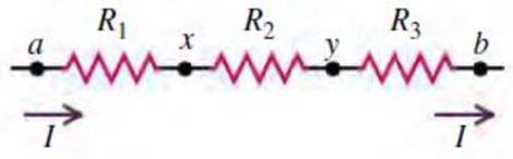
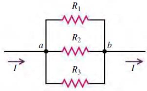
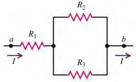
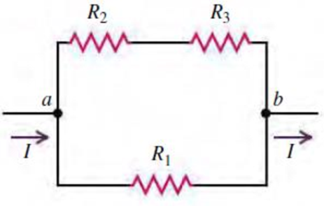
Suppose all three of the resistors shown in Fig. 26.1 have the same resistance, so R1 = R2 = R3 = R. Rank the four arrangements shown in parts (a)–(d) of Fig. 26.1 in order of their equivalent resistance, from highest to lowest.
- (a) R1, R2, and R3 in series
- (b) R1, R2, and R3 in parallel
- (c) R1 in series with parallel combination of R2 and R3
- (d) R1 in parallel with series combination of R2 and R3
Expert Solution & Answer

Learn your wayIncludes step-by-step video

schedule06:43
Students have asked these similar questions
In the figure the ideal batteries have emfs 1 = 26 V and 2 = 7.0 V and the resistors have resistances R1 = 4.2 Ω and R2 = 8.3 Ω. What are (a) the current, the energy dissipation rate in (b) resistor 1 and (c) resistor 2, and the energy transfer rate in (d) battery 1 and (e) battery 2? Is energy being supplied or absorbed by (f) battery 1 and (g) battery 2?
In the figure the ideal batteries have emfs 1 = 14 V and 2 = 6.0 V and the resistors have resistances R1 = 5.2 Ω and R2 = 8.9 Ω. What is the energy transfer rate in (d) battery 1 and (e) battery 2? Is energy being supplied or absorbed by (f) battery 1 and (g) battery 2?
Find the current in the R3 resistor in the drawing (V11 = 16.0 V, V22 = 18.0 V, V33 = 19.0 V, R11 = 1.80 Ω, R22 = 2.30 Ω, and R33 = 2.90 Ω).
Chapter 26 Solutions
University Physics with Modern Physics (14th Edition)
Ch. 26.1 - Suppose all three of the resistors shown in Fig....Ch. 26.2 - Subtract Eq. (1) from Eq. (2) in Example 26.6. To...Ch. 26.3 - You want to measure the current through and the...Ch. 26.4 - The energy stored in a capacitor is equal to...Ch. 26.5 - To prevent the circuit breaker in Example 26.14...Ch. 26 - In which 120-V light bulb does the filament have...Ch. 26 - Two 120-V light bulbs, one 25-W and one 200-W,...Ch. 26 - You connect a number of identical light bulbs to a...Ch. 26 - In the circuit shown in Fig. Q26.4, three...Ch. 26 - If two resistors R1 and R2 (R2 R1) are connected...
Ch. 26 - If two resistors R1 and R2 (R2 R1) are connected...Ch. 26 - A battery with no internal resistance is connected...Ch. 26 - A resistor consists of three identical metal...Ch. 26 - A light bulb is connected in the circuit shown in...Ch. 26 - A real battery, having nonnegligible internal...Ch. 26 - If the battery in Discussion Question Q26.10 is...Ch. 26 - Consider the circuit shown in Fig. Q26.12. What...Ch. 26 - Is it possible to connect resistors together in a...Ch. 26 - The battery in the circuit shown in Fig. Q26.14...Ch. 26 - In a two-cell flashlight, the batteries are...Ch. 26 - Identical light bulbs A, B, and C are connected as...Ch. 26 - The emf of a flashlight battery is roughly...Ch. 26 - Will the capacitors in the circuits shown in Fig....Ch. 26 - Verify that the time constant RC has units of...Ch. 26 - For very large resistances it is easy to construct...Ch. 26 - When a capacitor, battery, and resistor are...Ch. 26 - A uniform wire of resistance R is cut into three...Ch. 26 - A machine part has a resistor X protruding from an...Ch. 26 - A resistor with R1 = 25.0 is connected to a...Ch. 26 - A 42- resistor and a 20- resistor are connected in...Ch. 26 - A triangular array of resistors is shown in Fig....Ch. 26 - For the circuit shown in Fig. E26.6 both meters...Ch. 26 - For the circuit shown in Fig. E26.7 find the...Ch. 26 - Three resistors having resistances of 1.60 , 2.40...Ch. 26 - Now the three resistors of Exercise 26.8 are...Ch. 26 - Power Rating of a Resistor. The power rating of a...Ch. 26 - In Fig. E26.11, R1, = 3.00 , R2 = 6.00 , and R3=...Ch. 26 - In Fig. E26.11 the battery has emf 35.0 V and...Ch. 26 - Compute the equivalent resistance of the network...Ch. 26 - Compute the equivalent resistance of the network...Ch. 26 - In the circuit of Fig. E26.15, each resistor...Ch. 26 - Consider the circuit shown in Fig. E26.16. The...Ch. 26 - In the circuit shown in Fig. E26.17, the voltage...Ch. 26 - In the circuit shown in Fig. E26.18, = 36.0 V,...Ch. 26 - CP In the circuit in Fig. E26.19, a 20.0- resistor...Ch. 26 - In the circuit shown in Fig. E26.20, the rate at...Ch. 26 - Light Bulbs in Series and in Parallel. Two light...Ch. 26 - Light Bulbs in Series. A 60-W, 120-V light bulb...Ch. 26 - In the circuit shown in Fig. E26.23, ammeter A1...Ch. 26 - The batteries shown in the circuit in Fig. E26.24...Ch. 26 - In the circuit shown in Fig. E26.25 find (a) the...Ch. 26 - Find the emfs 1 and 2 in the circuit of Fig....Ch. 26 - In the circuit shown in Fig. E26.27, find (a) the...Ch. 26 - In the circuit shown in Fig. E26.28, find (a) the...Ch. 26 - The 10.00-V battery in Fig. E26.28 is removed from...Ch. 26 - The 5.00-V battery in Fig. E26.28 is removed from...Ch. 26 - In the circuit shown in Fig. E26.31 the batteries...Ch. 26 - In the circuit shown in Fig. E26.32 both batteries...Ch. 26 - In the circuit shown in Fig. E26.33 all meters are...Ch. 26 - In the circuit shown in Fig. E26.34, the 6.0-...Ch. 26 - The resistance of a galvanometer coil is 25.0 ,...Ch. 26 - The resistance of the coil of a pivoted coil...Ch. 26 - A circuit consists of a series combination of...Ch. 26 - A galvanometer having a resistance of 25.0 has a...Ch. 26 - A capacitor is charged to a potential of 12.0 V...Ch. 26 - You connect a battery, resistor, and capacitor as...Ch. 26 - A 4.60-F capacitor that is initially uncharged is...Ch. 26 - You connect a battery, resistor, and capacitor as...Ch. 26 - CP In the circuit shown in Fig. E26.43 both...Ch. 26 - A 12.4-F capacitor is connected through a 0.895-M...Ch. 26 - An emf source with = 120 V, a resistor with R =...Ch. 26 - A resistor and a capacitor are connected in series...Ch. 26 - CP In the circuit shown in Fig. E26.47 each...Ch. 26 - A 1.50-F capacitor is charging through a 12.0-...Ch. 26 - In the circuit in Fig. E26.49 the capacitors are...Ch. 26 - A 12.0-F capacitor is charged to a potential of...Ch. 26 - In the circuit shown in Fig. E26.51, C = 5.90 F, ...Ch. 26 - Prob. 26.52ECh. 26 - A 1500-W electric beater is plugged into the...Ch. 26 - In Fig. P26.54, the battery has negligible...Ch. 26 - The two identical light bulbs in Example 26.2...Ch. 26 - Each of the three resistors in Fig. P26.56 has a...Ch. 26 - (a) Find the potential of point a with respect to...Ch. 26 - CP For the circuit shown in Fig. P26.58 a 20.0-...Ch. 26 - Calculate the three currents I1, I2, and I3...Ch. 26 - What must the emf in Fig. P26.60 be in order for...Ch. 26 - Find the current through each of the three...Ch. 26 - (a) Find the current through the battery and each...Ch. 26 - Consider the circuit shown in Fig. P26.63. (a)...Ch. 26 - In the circuit shown in Fig. P26.64, = 24.0 V,...Ch. 26 - In the circuit shown in Fig. P26.65, the current...Ch. 26 - In the circuit shown in Fig. P26.66 all the...Ch. 26 - Figure P26.67 employs a convention often used in...Ch. 26 - Three identical resistors are connected in series....Ch. 26 - A resistor R1 consumes electrical power P1 when...Ch. 26 - The capacitor in Fig. F26.70 is initially...Ch. 26 - A 2.00-F capacitor that is initially uncharged is...Ch. 26 - A 6.00-F capacitor that is initially uncharged is...Ch. 26 - Point a in Fig. P26.73 is maintained at a constant...Ch. 26 - The Wheatstone Bridge. The circuit shown in Fig....Ch. 26 - (See Problem 26.67.) (a) What is the potential of...Ch. 26 - A 2.36-F capacitor that is initially uncharged is...Ch. 26 - A 224- resistor and a 589- resistor are connected...Ch. 26 - A resistor with R = 850 is connected to the...Ch. 26 - A capacitor that is initially uncharged is...Ch. 26 - DATA You set up the circuit shown in Fig. 26.22a,...Ch. 26 - DATA You set up the circuit shown in Fig. 26.20....Ch. 26 - DATA The electronics supply company where you work...Ch. 26 - An Infinite Network. As shown in Fig. P26.83, a...Ch. 26 - Suppose a resistor R lies along each edge of a...Ch. 26 - BIO Attenuator Chains and Axons. The infinite...Ch. 26 - Assume that a typical open ion channel spanning an...Ch. 26 - In a simple model of an axon conducting a nerve...Ch. 26 - Cell membranes across a wide variety of organisms...
Additional Science Textbook Solutions
Find more solutions based on key concepts
l. Suppose you have the uniformly charged cube in FIGURE Q24.1. Can you use symmetry alone to deduce the shape ...
Physics for Scientists and Engineers: A Strategic Approach with Modern Physics (4th Edition)
Explain all answers clearly, with complete sentences and proper essay structure if needed. An asterisk(*) desig...
Cosmic Perspective Fundamentals
When cant we see the crystals in rocks?
Conceptual Integrated Science
Your 200-g cup of tea is boiling-hot. About how much ice should you add to bring it down to a comfortable sippi...
An Introduction to Thermal Physics
22. Ultrasound can be used to deliver energy to tissues for therapy. It can penetrate tissue to a depth approxi...
College Physics: A Strategic Approach (4th Edition)
In Fig. 25.28, take all resistors to be 1 k Find the current in the vertical resistor when a 6.0-V battery is c...
Essential University Physics: Volume 2 (3rd Edition)
Knowledge Booster


Learn more about
Need a deep-dive on the concept behind this application? Look no further. Learn more about this topic, physics and related others by exploring similar questions and additional content below.Similar questions
- If the terminals of a battery with zero internal resistance are connected across two identical resistors in series, the total power delivered by the battery is 8.00 W. If the same battery is connected across the same resistors in parallel, what is the total power delivered by the battery? (a) 16.0 W (b) 32.0 W (c) 2.00 W (d) 4.00 W (e) none of those answersarrow_forwardThe power dissipated in a resistor is given by P = V2/R, which means power decreases if resistance increases. Yet this power is also given by P = I2R, which means power increases if resistance increases. Explain why there is no contradiction here.arrow_forwardPower P0 = I0 V0 is delivered to a resistor of resistance R0. If the resistance is doubled (Rnew = 2R0) while the voltage is adjusted such that the current is constant, what are the ratios (a) Pnew/P0 and (b) Vnew/V0? If, instead, the resistance is held constant while Pnew = 2P0, what are the ratios (c) Vnew/V0, and (d) Inew/I0?arrow_forward
- A 12.0-V emf automobile battery has a terminal voltage of 16.0 V when being charged by a current of 10.0 A. (a) What is the battery’s internal resistance? (b) What power is dissipated inside the battery? (c) At what rate (in °C/min ) will its temperature increase if its mass is 20.0 kg and it has a specific heat of 0.300 kcal/kg • °C, assuming no heat escapes?arrow_forwardElectric current I enters a node with three resistors connected in parallel (Fig. CQ18.5). Which one of the following is correct? (a) I1 = I and I2 = I3 = 0. (b) I2 I1 and I2 I3. (c) V1 V2 V3 (d) I1 I2 I3 0. Figure CQ18.5arrow_forwardWhen the switch is open in Figure 18.8, power Po is delivered to the resistor R1. When the switch is closed, which of the following is true about the power Pc delivered to R1? (Neglect the internal resistance of the battery.) (a) Pc Po (b) Pc = Po (c) Pc Po Figure 18.8 (Quick Quizzes 18.5 and 18.6)arrow_forward
- A child's electronic toy is supplied by three 1.58-V alkaline cells having internal resistances of 0.0200 inseries with a 1.53-V carbon-zinc dry cell having a 0.100- internal resistance. The load resistance is 10.0 . (a) Draw a circuit diagram of the toy and itsbatteries, (b) What current flows? (c) How much power is supplied to the load? (d) What is the internal resistance of the dry cell if it goes bad, resulting in only 0.500 W being supplied to the load?arrow_forward1. A 10 μF capacitor is connected in series with a 5 Ω resistor and a battery of negligible internal resistance and emf 6 V. After a long time, if the charging battery is removed and the capacitor is immediately connected across the 5 Ω resistor, the initial value of the discharge current is a. 1.2b. 0.6c. 0.3d. 0.832. Resistances of 2.0 Ω, 4.0 Ω, and 6.0 Ω and a 24-V emf device are all in parallel. The current in the 2.0-Ω resistor is: 3. Solve and find the value of Iarrow_forward
arrow_back_ios
arrow_forward_ios
Recommended textbooks for you
 College PhysicsPhysicsISBN:9781938168000Author:Paul Peter Urone, Roger HinrichsPublisher:OpenStax College
 Physics for Scientists and Engineers: Foundations...PhysicsISBN:9781133939146Author:Katz, Debora M.Publisher:Cengage Learning
 College PhysicsPhysicsISBN:9781285737027Author:Raymond A. Serway, Chris VuillePublisher:Cengage Learning
 College PhysicsPhysicsISBN:9781305952300Author:Raymond A. Serway, Chris VuillePublisher:Cengage Learning
 Principles of Physics: A Calculus-Based TextPhysicsISBN:9781133104261Author:Raymond A. Serway, John W. JewettPublisher:Cengage Learning
College Physics
Physics
ISBN:9781938168000
Author:Paul Peter Urone, Roger Hinrichs
Publisher:OpenStax College
Physics for Scientists and Engineers: Foundations...
Physics
ISBN:9781133939146
Author:Katz, Debora M.
Publisher:Cengage Learning
College Physics
Physics
ISBN:9781285737027
Author:Raymond A. Serway, Chris Vuille
Publisher:Cengage Learning
College Physics
Physics
ISBN:9781305952300
Author:Raymond A. Serway, Chris Vuille
Publisher:Cengage Learning
Principles of Physics: A Calculus-Based Text
Physics
ISBN:9781133104261
Author:Raymond A. Serway, John W. Jewett
Publisher:Cengage Learning
How To Solve Any Resistors In Series and Parallel Combination Circuit Problems in Physics; Author: The Organic Chemistry Tutor;https://www.youtube.com/watch?v=eFlJy0cPbsY;License: Standard YouTube License, CC-BY