
Videos
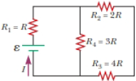
Four resistors are connected to a battery as shown in Figure P27.15. (a) Determine the potential difference across each resistor in terms of ε. (b) Determine the current in each resistor in terms of I. (c) What If? If R3 is increased, explain what happens to the current in each of the resistors. (d) In the limit that R3 → ∞, what are the new values of the current in each resistor in terms of I, the original current in the battery?
Figure P27.15
(a)
Answer to Problem 15P
Explanation of Solution
The resistors
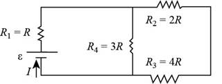
Figure (1)
Formula to calculate the resistance across the circuit when resistors
Here,
Substitute
Thus, the resistance across the circuit when resistors
The resistors
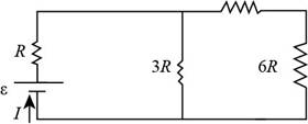
Figure (2)
Formula to calculate the resistance when the resistors are connected in parallel is,
Here,
Substitute
Thus, the value of the resistance when the resistors are connected in parallel is
The resistors
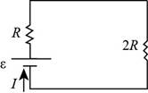
Figure (3)
Formula to calculate the equivalent resistance across the circuit is,
Here,
Substitute
Thus, the equivalent resistance across the circuit is
The equivalent resistance is shown in the figure 4.
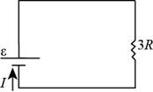
Figure (4)
Formula to calculate the current across the circuit is,
Here,
Substitute
Thus, the current across the circuit is
Formula to calculate the voltage across the
Here,
Substitute
Thus, the voltage across the
Thus, the voltage across the
Formula to calculate the voltage across the
Here,
Substitute
Thus, the voltage across the
Formula to calculate the current across the
Here,
Substitute
Thus, the current across the
Formula to calculate the current across the
Here,
Substitute
Thus, the current across the
Formula to calculate the voltage across the
Here,
Substitute
Thus, the voltage across the
Formula to calculate the voltage across the
Here,
Substitute
Thus, the voltage across the
Conclusion:
Therefore, the potential difference across
(b)
Answer to Problem 15P
Explanation of Solution
Formula to calculate the value of
Substitute
Thus, the value of
Formula to calculate the current across the
Here,
Substitute
Substitute
Thus, the current across the
Formula to calculate the current across the
Here,
Substitute
Substitute
Thus, the current across the
Formula to calculate the current across the
Here,
Substitute
Substitute
Thus, the current across the
Formula to calculate the current across the
Here,
Substitute
Substitute
Thus, the current across the
Conclusion:
Therefore, the current across
(c)
Answer to Problem 15P
Explanation of Solution
If the value of the
Since, the current remains same in series combination. So, the value of current across
If the value of the
Thus, the current across the
Conclusion:
Therefore, the value of current across
(d)
Answer to Problem 15P
Explanation of Solution
If
Here,
The resistors
Formula to calculate the resistance across the circuit when resistors
Here,
Substitute
Thus, the resistance across the circuit when resistors
From equation (11), the value of
From equation (12), formula to calculate the current across the
Here,
Substitute
Thus, the current across the
As the resistors
Here,
Thus, the original current in the battery is
Conclusion:
Therefore, the current across
Want to see more full solutions like this?
Chapter 27 Solutions
Physics for Scientists and Engineers


- A lightbulb is connected to a variable power supply. As the potential across the bulb is varied, the resulting current and the filaments temperature are measured. The data are listed in Table P28.38. a. Find R for each entry in Table P28.38, and then plot R as a function of T. b. Assume that room temperature is at 293 K. Find R0 (resistance at room temperature). Comment on your result.arrow_forwardFour resistors are connected to a battery as shown in Figure P21.40. The current in the battery is I, the battery emf is , and the resistor values are R1 = R, R2 = 2R, R3 = 4R, and R4 = 3R. (a) Rank the resistors according to the potential difference across them, from largest to smallest. Note any cases of equal potential differences. (b) Determine the potential difference across each resistor in terms of . (c) Rank the resistors according to the current in them, from largest to smallest. Note any cases of equal currents. (d) Determine the current in each resistor in terms of I. (e) If R3 is increased, what happens to the current in each of the resistors? (f) In the limit that R3 , what are the new values of the current in each resistor in terms of I, the original current in the battery? Figure P21.40arrow_forwardA regular tetrahedron is a pyramid with a triangular base and triangular sides as shown in Figure P28.73. Imagine the six straight lines in Figure P28.73 are each 10.0- resistors, with junctions at the four vertices. A 12.0-V battery is connected to any two of the vertices. Find (a) the equivalent resistance of the tetrahedron between these vertices and (b) the current in the batten.arrow_forward
- In the figure below, the ideal batteries have emfs ℰ1 = 12 V, ℰ2 = 6.0 V, and the resistors have resistances R1 = 4.0 Ω and R2 = 5.0 Ω. (a) What is the current in the circuit? _________A(b) What is the dissipation rate in resistor 1? _________W(c) What is the dissipation rate in resistor 2? __________W (please show units when you work this out so that I can follow it easier.)arrow_forwarda) The resistance between two well-separated points on the human body is about1.5 x 10. If a potential difference of 120 V is applied across these points, how much current is generated? (b) If the skin is wet, the resistance drops to 5.0 x 10. What will the current be in this case for an applied potential difference of 120 V? blank2 - Numeric Answerarrow_forwardWhen you connect an unknown resistor across the terminals of a 1.50 VV AAA battery having negligible internal resistance, you measure a current of 17.0 mAmA flowing through it. Part A What is the resistance of this resistor? Part B If you now place the resistor across the terminals of a 12.6 VV car battery having no internal resistance, how much current will flow? Part C You now put the resistor across the terminals of an unknown battery of negligible internal resistance and measure a current of 0.483 AA flowing through it. What is the potential difference across the terminals of the battery?arrow_forward
- A photoresistor, whose resistance decreases with light intensity, is connected in the circuit as shown. On a sunny day, the photoresistor has a resistance of 0.56 kΩ. On a cloudy day, the resistance rises to 4.0 kΩ. At night, the resistance is 20 kΩ.a. What does the voltmeter read for each of these conditions?b. Does the voltmeter reading increase or decrease as the light intensity increases?arrow_forward(a) A defibrillator sends a 6.00-A current through the chest of a patient by applying a 10,000-V potential as in the figure below. What is the resistance of the path? (b) The defibrillator paddles make contact with the patient through a conducting gel that greatly reduces the path resistance. Discuss thedifficulties that would ensue if a larger voltage were used to produce the same current through the patient, but with the path having perhaps 50 times the resistance. (Hint: The current must be about the same, so a higher voltage would imply greater power. Use this equation for power: P = I 2R .)arrow_forwardA battery with E=39 V and negligible internal resistance is connected to one's voltage conductor as shown in the figure. R1 and R2 are given. a) What is the voltage U2 if no external load is connected? b)How big will the current be between A and B if these connection points are short-circuited. c) How large is U2 if a load with resistance 68 is connected between A and B? d) What is the power of the circuit if a load with resistance 68 is connected between A and B?arrow_forward
 Physics for Scientists and Engineers with Modern ...PhysicsISBN:9781337553292Author:Raymond A. Serway, John W. JewettPublisher:Cengage Learning
 Physics for Scientists and EngineersPhysicsISBN:9781337553278Author:Raymond A. Serway, John W. JewettPublisher:Cengage Learning
 Principles of Physics: A Calculus-Based TextPhysicsISBN:9781133104261Author:Raymond A. Serway, John W. JewettPublisher:Cengage Learning
 Physics for Scientists and Engineers: Foundations...PhysicsISBN:9781133939146Author:Katz, Debora M.Publisher:Cengage Learning
 Physics for Scientists and Engineers, Technology ...PhysicsISBN:9781305116399Author:Raymond A. Serway, John W. JewettPublisher:Cengage Learning