
Physics for Scientists and Engineers
10th Edition
ISBN: 9781337553278
Author: Raymond A. Serway, John W. Jewett
Publisher: Cengage Learning
expand_more
expand_more
format_list_bulleted
Videos
Textbook Question
Chapter 27, Problem 20P
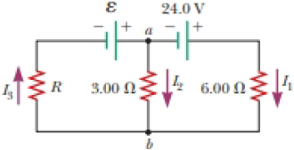
In the circuit of Figure P27.20, the current I1 = 3.00 A and the values of ε for the ideal battery and R are unknown. What are the currents (a) I2 and (b) I3? (c) Can you find the values of ε and R? If so, find their values. If not, explain.
Figure P27.20
Expert Solution & Answer

Trending nowThis is a popular solution!

Chapter 27 Solutions
Physics for Scientists and Engineers
Ch. 27.1 - To maximize the percentage of the power from the...Ch. 27.2 - With the switch in the circuit of Figure 27.4a...Ch. 27.2 - With the switch in the circuit of Figure 27.6a...Ch. 27.2 - Prob. 27.4QQCh. 27.4 - Consider the circuit in Figure 27.17 and assume...Ch. 27 - Two 1.50-V batterieswith their positive terminals...Ch. 27 - As in Example 27.2, consider a power supply with...Ch. 27 - Figure P27.3 shows the interior of a three-way...Ch. 27 - Prob. 4PCh. 27 - Consider the two circuits shown in Figure P27.5 in...
Ch. 27 - Consider strings of incandescent lights that are...Ch. 27 - You are working at an electronics fabrication...Ch. 27 - In your new job at an engineering company, your...Ch. 27 - A battery with = 6.00 V and no internal...Ch. 27 - A battery with emf and no internal resistance...Ch. 27 - Todays class on current and resistance is about to...Ch. 27 - Why is the following situation impossible? A...Ch. 27 - Calculate the power delivered to each resistor in...Ch. 27 - For the purpose of measuring the electric...Ch. 27 - Four resistors are connected to a battery as shown...Ch. 27 - You have a faculty position at a community college...Ch. 27 - The circuit shown in Figure P27.17 is connected...Ch. 27 - The following equations describe an electric...Ch. 27 - Taking R = 1.00 k and = 250 V in Figure P27.19,...Ch. 27 - In the circuit of Figure P27.20, the current I1 =...Ch. 27 - (a) Can the circuit shown in Figure P27.21 be...Ch. 27 - For the circuit shown in Figure P27.22, we wish to...Ch. 27 - An uncharged capacitor and a resistor are...Ch. 27 - Show that the time constant in Equation 27.20 has...Ch. 27 - In the circuit of Figure P27.25, the switch S has...Ch. 27 - In the circuit of Figure P27.25, the switch S has...Ch. 27 - A 10.0-F capacitor is charged by a 10.0-V battery...Ch. 27 - Show that the integral 0e2t/RCdtin Example 27.11...Ch. 27 - You and your roommates are studying hard for your...Ch. 27 - Prob. 30PCh. 27 - Turn on your desk lamp. Pick up the cord, with...Ch. 27 - Four resistors are connected in parallel across a...Ch. 27 - Find the equivalent resistance between points a...Ch. 27 - The circuit in Figure P27.34a consists of three...Ch. 27 - The circuit in Figure P27.35 has been connected...Ch. 27 - The resistance between terminals a and b in Figure...Ch. 27 - (a) Calculate the potential difference between...Ch. 27 - Why is the following situation impossible? A...Ch. 27 - When two unknown resistors are connected in series...Ch. 27 - When two unknown resistors are connected in series...Ch. 27 - The circuit in Figure P27.41 contains two...Ch. 27 - Two resistors R1 and R2 are in parallel with each...Ch. 27 - A power supply has an open-circuit voltage of 40.0...Ch. 27 - A battery is used to charge a capacitor through a...Ch. 27 - An ideal voltmeter connected across a certain...Ch. 27 - (a) Determine the equilibrium charge on the...Ch. 27 - In Figure P27.47, suppose the switch has been...Ch. 27 - Figure P27.48 shows a circuit model for the...Ch. 27 - The student engineer of a campus radio station...Ch. 27 - A voltage V is applied to a series configuration...Ch. 27 - The switch in Figure P27.51a closes when Vc23Vand...
Knowledge Booster


Learn more about
Need a deep-dive on the concept behind this application? Look no further. Learn more about this topic, physics and related others by exploring similar questions and additional content below.Similar questions
- Figure P29.45 shows five resistors connected between terminals a and b. a. What is the equivalent resistance of this combination of resistors? b. What is the current through each resistor if a 24.0-V battery is connected across the terminals?arrow_forwardTwo 1.50-V batterieswith their positive terminals in the same directionare inserted in series into a flashlight. One battery has an internal resistance of 0.255 , and the other has an internal resistance of 0.153 . When the switch is closed, the bulb carries a current of 600 mA. (a) What is the bulbs resistance? (b) What fraction of the chemical energy transformed appears as internal energy in the batteries?arrow_forward(a) Can the circuit shown in Figure P18.29 be reduced to a single resistor connected to the batteries? Explain. (b) Find the magnitude of the current and its direction in each resistor. Figure P18.29arrow_forward
- Four resistors are connected to a battery as shown in Figure P27.15. (a) Determine the potential difference across each resistor in terms of . (b) Determine the current in each resistor in terms of I. (c) What If? If R3 is increased, explain what happens to the current in each of the resistors. (d) In the limit that R3 , what are the new values of the current in each resistor in terms of I, the original current in the battery? Figure P27.15arrow_forwardA battery is used to charge a capacitor through a resistor as shown in Figure P27.44. Show that half the energy supplied by the battery appears as internal energy in the resistor and half is stored in the capacitor. Figure P27.44arrow_forwardFour resistors are connected to a battery as shown in Figure P21.40. The current in the battery is I, the battery emf is , and the resistor values are R1 = R, R2 = 2R, R3 = 4R, and R4 = 3R. (a) Rank the resistors according to the potential difference across them, from largest to smallest. Note any cases of equal potential differences. (b) Determine the potential difference across each resistor in terms of . (c) Rank the resistors according to the current in them, from largest to smallest. Note any cases of equal currents. (d) Determine the current in each resistor in terms of I. (e) If R3 is increased, what happens to the current in each of the resistors? (f) In the limit that R3 , what are the new values of the current in each resistor in terms of I, the original current in the battery? Figure P21.40arrow_forward
- For the network in Figure P18.60, show that the resistance between points a and b is Rab=2717. (Hint: Connect a battery with emf across points a and b and determine /I, where I is the current in the battery.) Figure P18.60arrow_forwardThe resistance between terminals a and b in Figure P27.36 is 75.0 . If the resistors labeled R have the same value, determine R. Figure P27.36arrow_forwardIn the circuit of Figure P21.51, determine (a) the current in each resistor and (b) the potential difference across the 200- resistor. Figure P21.51arrow_forward
- A lightbulb is connected to a variable power supply. As the potential across the bulb is varied, the resulting current and the filaments temperature are measured. The data are listed in Table P28.38. a. Find R for each entry in Table P28.38, and then plot R as a function of T. b. Assume that room temperature is at 293 K. Find R0 (resistance at room temperature). Comment on your result.arrow_forwardA student makes a homemade resistor from a graphite pencil 5.00 cm long, where the graphite is 0.05 mm indiameter. The resistivity of the graphite is =1.38102/m . The homemade resistor is place inseries with a switch, a 10.00-mF capacitor and a 0.50-V power source, (a) What is the BC time constant of the circuit? (b) What is the potential drop across the pencil 1.00 s after the switch is closed?arrow_forwardWhat is the equivalent resistance between points a and b of the six resistors shown in Figure P29.70? FIGURE P29.70arrow_forward
arrow_back_ios
SEE MORE QUESTIONS
arrow_forward_ios
Recommended textbooks for you
 Physics for Scientists and Engineers with Modern ...PhysicsISBN:9781337553292Author:Raymond A. Serway, John W. JewettPublisher:Cengage Learning
 Physics for Scientists and EngineersPhysicsISBN:9781337553278Author:Raymond A. Serway, John W. JewettPublisher:Cengage Learning
 Principles of Physics: A Calculus-Based TextPhysicsISBN:9781133104261Author:Raymond A. Serway, John W. JewettPublisher:Cengage Learning
 College PhysicsPhysicsISBN:9781285737027Author:Raymond A. Serway, Chris VuillePublisher:Cengage Learning
 College PhysicsPhysicsISBN:9781305952300Author:Raymond A. Serway, Chris VuillePublisher:Cengage Learning
 Physics for Scientists and Engineers: Foundations...PhysicsISBN:9781133939146Author:Katz, Debora M.Publisher:Cengage Learning
Physics for Scientists and Engineers with Modern ...
Physics
ISBN:9781337553292
Author:Raymond A. Serway, John W. Jewett
Publisher:Cengage Learning
Physics for Scientists and Engineers
Physics
ISBN:9781337553278
Author:Raymond A. Serway, John W. Jewett
Publisher:Cengage Learning
Principles of Physics: A Calculus-Based Text
Physics
ISBN:9781133104261
Author:Raymond A. Serway, John W. Jewett
Publisher:Cengage Learning
College Physics
Physics
ISBN:9781285737027
Author:Raymond A. Serway, Chris Vuille
Publisher:Cengage Learning
College Physics
Physics
ISBN:9781305952300
Author:Raymond A. Serway, Chris Vuille
Publisher:Cengage Learning
Physics for Scientists and Engineers: Foundations...
Physics
ISBN:9781133939146
Author:Katz, Debora M.
Publisher:Cengage Learning
How To Solve Any Resistors In Series and Parallel Combination Circuit Problems in Physics; Author: The Organic Chemistry Tutor;https://www.youtube.com/watch?v=eFlJy0cPbsY;License: Standard YouTube License, CC-BY