
Physics for Scientists and Engineers
10th Edition
ISBN: 9781337553278
Author: Raymond A. Serway, John W. Jewett
Publisher: Cengage Learning
expand_more
expand_more
format_list_bulleted
Videos
Textbook Question
Chapter 27.2, Problem 27.2QQ
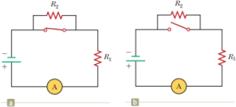
With the switch in the circuit of Figure 27.4a closed, there is no current in R2 because the current has an alternate zero-resistance path through the switch. There is current in R1, and this current is measured with the ammeter (a device for measuring current) at the bottom of the circuit. If the switch is opened (Fig. 27.4b), there is current in R2. What happens to the reading on the ammeter when the switch is opened? (a) The reading goes up. (b) The reading goes down. (c) The reading does not change.
Figure 27.4 (Quick Quiz 27.2) What happens when the switch is opened?
Expert Solution & Answer

Trending nowThis is a popular solution!

Students have asked these similar questions
Consider the RL circuit in the figure with R=10.00 Ω, L1=1.80 H, L2=3.90 H, and V=5.0 V. At time t=0, the switch is closed to connect the circuit to a constant emf. How long (in seconds) does it take for the current to reach a value of Imax/2.71828 of its maximum value, where Imax is the maximum current through the circuit?
In the figure below, R1 =10.0kΩ, R2 =15.0kΩ, C=0.40μF, and the ideal battery has an emf E=20.0V. First, the switch is closed until the system reaches steady state; then, the switch is opened at time t = 0 and the capacitor starts to discharge. What is the current in R2 at t = 3.00 ms?
The capacitor in the figure below is uncharged for
t < 0.
If = 8.02 V, R = 58.9 Ω, and C = 4.00 µF, use Kirchhoff's loop rule to find the current (in A) through the resistor at the following times.
The circuit is a rectangular loop. The bottom side of the loop has a battery labeled emf ℰ, oriented with the positive terminal to the right of the negative terminal. The right side has a resistor R. The top side contains an open switch S. The left side has a capacitor C.
HINT
(a)
t = 0,
when the switch is closed
A
(b)
t = ?,
one time constant after the switch is closed
A
Chapter 27 Solutions
Physics for Scientists and Engineers
Ch. 27.1 - To maximize the percentage of the power from the...Ch. 27.2 - With the switch in the circuit of Figure 27.4a...Ch. 27.2 - With the switch in the circuit of Figure 27.6a...Ch. 27.2 - Prob. 27.4QQCh. 27.4 - Consider the circuit in Figure 27.17 and assume...Ch. 27 - Two 1.50-V batterieswith their positive terminals...Ch. 27 - As in Example 27.2, consider a power supply with...Ch. 27 - Figure P27.3 shows the interior of a three-way...Ch. 27 - Prob. 4PCh. 27 - Consider the two circuits shown in Figure P27.5 in...
Ch. 27 - Consider strings of incandescent lights that are...Ch. 27 - You are working at an electronics fabrication...Ch. 27 - In your new job at an engineering company, your...Ch. 27 - A battery with = 6.00 V and no internal...Ch. 27 - A battery with emf and no internal resistance...Ch. 27 - Todays class on current and resistance is about to...Ch. 27 - Why is the following situation impossible? A...Ch. 27 - Calculate the power delivered to each resistor in...Ch. 27 - For the purpose of measuring the electric...Ch. 27 - Four resistors are connected to a battery as shown...Ch. 27 - You have a faculty position at a community college...Ch. 27 - The circuit shown in Figure P27.17 is connected...Ch. 27 - The following equations describe an electric...Ch. 27 - Taking R = 1.00 k and = 250 V in Figure P27.19,...Ch. 27 - In the circuit of Figure P27.20, the current I1 =...Ch. 27 - (a) Can the circuit shown in Figure P27.21 be...Ch. 27 - For the circuit shown in Figure P27.22, we wish to...Ch. 27 - An uncharged capacitor and a resistor are...Ch. 27 - Show that the time constant in Equation 27.20 has...Ch. 27 - In the circuit of Figure P27.25, the switch S has...Ch. 27 - In the circuit of Figure P27.25, the switch S has...Ch. 27 - A 10.0-F capacitor is charged by a 10.0-V battery...Ch. 27 - Show that the integral 0e2t/RCdtin Example 27.11...Ch. 27 - You and your roommates are studying hard for your...Ch. 27 - Prob. 30PCh. 27 - Turn on your desk lamp. Pick up the cord, with...Ch. 27 - Four resistors are connected in parallel across a...Ch. 27 - Find the equivalent resistance between points a...Ch. 27 - The circuit in Figure P27.34a consists of three...Ch. 27 - The circuit in Figure P27.35 has been connected...Ch. 27 - The resistance between terminals a and b in Figure...Ch. 27 - (a) Calculate the potential difference between...Ch. 27 - Why is the following situation impossible? A...Ch. 27 - When two unknown resistors are connected in series...Ch. 27 - When two unknown resistors are connected in series...Ch. 27 - The circuit in Figure P27.41 contains two...Ch. 27 - Two resistors R1 and R2 are in parallel with each...Ch. 27 - A power supply has an open-circuit voltage of 40.0...Ch. 27 - A battery is used to charge a capacitor through a...Ch. 27 - An ideal voltmeter connected across a certain...Ch. 27 - (a) Determine the equilibrium charge on the...Ch. 27 - In Figure P27.47, suppose the switch has been...Ch. 27 - Figure P27.48 shows a circuit model for the...Ch. 27 - The student engineer of a campus radio station...Ch. 27 - A voltage V is applied to a series configuration...Ch. 27 - The switch in Figure P27.51a closes when Vc23Vand...
Knowledge Booster


Learn more about
Need a deep-dive on the concept behind this application? Look no further. Learn more about this topic, physics and related others by exploring similar questions and additional content below.Similar questions
- How do you solve this question? The first question's answer is c) 3.0 T but I can't seem to get the right answer if I attempt use the equation emf = (BA)/t. Is t 1.25, 5, or something else?arrow_forwardAfter being closed for a long time, the switch S in the circuit shown in the figure below is thrown open at t = 0. In the circuit, E= 24.0 V, RA = 3.90 kΩ, RB = 7.20 kΩ, and L = 646 mH.arrow_forwardIn the circuit of Figure P27.25, the switch S has been open for a long time. It is then suddenly closed. Take = 10.0 V, R1 = 50.0 k, R2 = 100 k, and C = 10.0 F. Determine the time constant (a) before the switch is closed and (b) after the switch is closed. (c) Let the switch be closed at t = 0. Determine the current in the switch as a function of time. Figure P27.25 Problems 25 and 26.arrow_forward
- In the circuit of Figure P27.25, the switch S has been open for a long time. It is then suddenly closed. Determine the time constant (a) before the switch is closed and (b) after the switch is closed. (c) Let the switch be closed at t = 0. Determine the current in the switch as a function of time. Figure P27.25 Problems 25 and 26.arrow_forwardWhen the switch is open in Figure 18.8, power Po is delivered to the resistor R1. When the switch is closed, which of the following is true about the power Pc delivered to R1? (Neglect the internal resistance of the battery.) (a) Pc Po (b) Pc = Po (c) Pc Po Figure 18.8 (Quick Quizzes 18.5 and 18.6)arrow_forwardWhen the switch is open in Figure 18.8, power Po is delivered to the resistor R1. When the switch is closed, which of the following is true about the power Pc delivered to R1? (Neglect the internal resistance of the battery.) (a) Pc Po (b) Pc = Po (c) Pc Po Figure 18.8 (Quick Quizzes 18.5 and 18.6)arrow_forward
- A motor in normal operation carries a direct current of 0.850 A when connected to a 120-V power supply. The resistance of the motor windings is 11.8 . While in normal operation, (a) what is the back emf generated by the motor? (b) At what rate is internal energy produced in the windings? (c) What If? Suppose a malfunction slops the motor shaft from rotating. At what rate will internal energy be produced in the windings in this case? (Most motors have a thermal switch that will turn off the motor to prevent overheating when this stalling occurs.)arrow_forwardWith the switch in the circuit of Figure 21.18a open, there is no current in R2. There is current in R1, however, and it is measured with the ammeter at the right side of the circuit. If the switch is closed (Fig. 21.18b), there is current in R2. What happens to the reading on the ammeter when the switch is closed? (a) The reading increases. (b) The reading decreases. (c) The reading does not change.arrow_forwardFind the direction of the current in the resistor shown in Figure P20.16 (a) at the instant the switch is closed, (b) after the switch has been closed for several minutes, and (c) at the instant the switch is opened. Figure P20.16arrow_forward
- A moving coil ammeter gives a full scale deflection for a current i = 60 mA and its coil has a resistance RC = 0.5 Ω. It is provided with a multiplier resistance Rm = 2.5 Ω added in series. What is the full scale deflection in volts of this modified ammeter? Select one: a. 30 mV b. 24 mV c. 150 mV d. 180 mVarrow_forwardThe circuit contains three resistors, A, B, and C, which have equal resistances. epsilon = 110V. Which resistor generates the most thermal energy after the switch is closed? a.B b.A c.All three generate the same amount of thermal energy. d.C e.A and Barrow_forwardIn the figure R1 = 9.81 kΩ, R2 = 15.4 kΩ, C = 0.433 μF, and the ideal battery has emf ε = 18.0 V. First, the switch is closed a long time so that the steady state is reached. Then the switch is opened at time t = 0. What is the current in resistor 2 at t = 3.60 ms?arrow_forward
arrow_back_ios
SEE MORE QUESTIONS
arrow_forward_ios
Recommended textbooks for you
 Principles of Physics: A Calculus-Based TextPhysicsISBN:9781133104261Author:Raymond A. Serway, John W. JewettPublisher:Cengage Learning
 College PhysicsPhysicsISBN:9781285737027Author:Raymond A. Serway, Chris VuillePublisher:Cengage Learning
 College PhysicsPhysicsISBN:9781305952300Author:Raymond A. Serway, Chris VuillePublisher:Cengage Learning
 Physics for Scientists and EngineersPhysicsISBN:9781337553278Author:Raymond A. Serway, John W. JewettPublisher:Cengage Learning
 Physics for Scientists and Engineers with Modern ...PhysicsISBN:9781337553292Author:Raymond A. Serway, John W. JewettPublisher:Cengage Learning
 Physics for Scientists and Engineers, Technology ...PhysicsISBN:9781305116399Author:Raymond A. Serway, John W. JewettPublisher:Cengage Learning
Principles of Physics: A Calculus-Based Text
Physics
ISBN:9781133104261
Author:Raymond A. Serway, John W. Jewett
Publisher:Cengage Learning
College Physics
Physics
ISBN:9781285737027
Author:Raymond A. Serway, Chris Vuille
Publisher:Cengage Learning
College Physics
Physics
ISBN:9781305952300
Author:Raymond A. Serway, Chris Vuille
Publisher:Cengage Learning
Physics for Scientists and Engineers
Physics
ISBN:9781337553278
Author:Raymond A. Serway, John W. Jewett
Publisher:Cengage Learning
Physics for Scientists and Engineers with Modern ...
Physics
ISBN:9781337553292
Author:Raymond A. Serway, John W. Jewett
Publisher:Cengage Learning
Physics for Scientists and Engineers, Technology ...
Physics
ISBN:9781305116399
Author:Raymond A. Serway, John W. Jewett
Publisher:Cengage Learning
What is Electromagnetic Induction? | Faraday's Laws and Lenz Law | iKen | iKen Edu | iKen App; Author: Iken Edu;https://www.youtube.com/watch?v=3HyORmBip-w;License: Standard YouTube License, CC-BY