
Videos
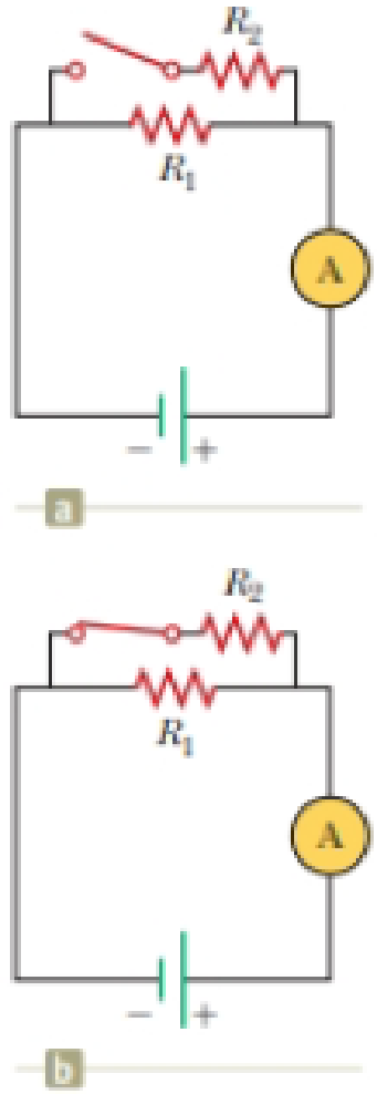
With the switch in the circuit of Figure 27.6a open, there is no current in R2. There is current in R1, however, and it is measured with the ammeter at the right side of the circuit. If the switch is closed (Fig. 27.6b), there is current in R2. What happens to the reading on the ammeter when the switch is closed? (a) The reading increases. (b) The reading decreases. (c) The reading does not change.
Figure 27.6 (Quick Quiz 27.3) What happens when the switch is closed?

Trending nowThis is a popular solution!

Chapter 27 Solutions
Physics for Scientists and Engineers with Modern Physics
Additional Science Textbook Solutions
University Physics Volume 1
College Physics: A Strategic Approach (3rd Edition)
Conceptual Integrated Science
University Physics with Modern Physics (14th Edition)
Schaum's Outline of College Physics, Twelfth Edition (Schaum's Outlines)
An Introduction to Thermal Physics


- Consider the RL circuit in the figure with R=10.00 Ω, L1=1.80 H, L2=3.90 H, and V=5.0 V. At time t=0, the switch is closed to connect the circuit to a constant emf. How long (in seconds) does it take for the current to reach a value of Imax/2.71828 of its maximum value, where Imax is the maximum current through the circuit?arrow_forwardThe capacitor in the figure below is uncharged for t < 0. If = 8.02 V, R = 58.9 Ω, and C = 4.00 µF, use Kirchhoff's loop rule to find the current (in A) through the resistor at the following times. The circuit is a rectangular loop. The bottom side of the loop has a battery labeled emf ℰ, oriented with the positive terminal to the right of the negative terminal. The right side has a resistor R. The top side contains an open switch S. The left side has a capacitor C. HINT (a) t = 0, when the switch is closed A (b) t = ?, one time constant after the switch is closed Aarrow_forwardAfter being closed for a long time, the switch S in the circuit shown in the figure below is thrown open at t = 0. In the circuit, E= 24.0 V, RA = 3.90 kΩ, RB = 7.20 kΩ, and L = 646 mH.arrow_forward
- In the circuit below, it is known that R1 = 10 kΩ, R2 = 15 kΩ, and C = 0.4 μF, and a battery with an Emf of 20 Volts. Initially, the connector (switch) is connected for a long time until it reaches a steady state. Then the switch is disconnected/opened at t = 0. What is the current flowing in resistor 2 at t = 4 ms?arrow_forwardIf the battery in the circuit below is 7.16V, resistor R1=331.15ΩΩ, and resistor R2=51.49ΩΩ, what is the magnitude of the current flowing through the circuit? Please give your answer in units of milli-Amps (mA).arrow_forwardIn the circuit below, the switch has been in the open position for a long time. At t=0, the switch is turned on. If the current at time t=3.3 ms reaches half of its maximum value, L=68 mH, and ℰ=17 V, find:the time constant τ= ms,the resistance R= Ω,the maximum value of the current, Imax= A.If the switch is open again, after what time, the current will reach the half of its value?t1/2= ms.arrow_forward
- When the switch is open in Figure 18.8, power Po is delivered to the resistor R1. When the switch is closed, which of the following is true about the power Pc delivered to R1? (Neglect the internal resistance of the battery.) (a) Pc Po (b) Pc = Po (c) Pc Po Figure 18.8 (Quick Quizzes 18.5 and 18.6)arrow_forwardIn the circuit of Figure P27.25, the switch S has been open for a long time. It is then suddenly closed. Take = 10.0 V, R1 = 50.0 k, R2 = 100 k, and C = 10.0 F. Determine the time constant (a) before the switch is closed and (b) after the switch is closed. (c) Let the switch be closed at t = 0. Determine the current in the switch as a function of time. Figure P27.25 Problems 25 and 26.arrow_forwardThe switch is closed in Figure 18.20. After a long time compared with the time constant, of the circuit, what will the current be in the 2- resistor? (a) 4 A (b) 3 A (c) 2 A (d) 1 A (c) More information is needed. Figure 18.20 (Quick Quiz 18.9)arrow_forward
- In the circuit of Figure P27.25, the switch S has been open for a long time. It is then suddenly closed. Determine the time constant (a) before the switch is closed and (b) after the switch is closed. (c) Let the switch be closed at t = 0. Determine the current in the switch as a function of time. Figure P27.25 Problems 25 and 26.arrow_forwardFind the direction of the current in the resistor shown in Figure P20.16 (a) at the instant the switch is closed, (b) after the switch has been closed for several minutes, and (c) at the instant the switch is opened. Figure P20.16arrow_forwardThe switch is closed in Figure 18.20. After a long time compared with the time constant, of the circuit, what will the current be in the 2- resistor? (a) 4 A (b) 3 A (c) 2 A (d) 1 A (c) More information is needed. Figure 18.20 (Quick Quiz 18.9)arrow_forward
 Principles of Physics: A Calculus-Based TextPhysicsISBN:9781133104261Author:Raymond A. Serway, John W. JewettPublisher:Cengage Learning
 Physics for Scientists and EngineersPhysicsISBN:9781337553278Author:Raymond A. Serway, John W. JewettPublisher:Cengage Learning
 Physics for Scientists and Engineers with Modern ...PhysicsISBN:9781337553292Author:Raymond A. Serway, John W. JewettPublisher:Cengage Learning
 College PhysicsPhysicsISBN:9781285737027Author:Raymond A. Serway, Chris VuillePublisher:Cengage Learning
 College PhysicsPhysicsISBN:9781305952300Author:Raymond A. Serway, Chris VuillePublisher:Cengage Learning