
Videos
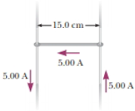
Consider the system pictured in Figure P28.26. A 15.0-cm horizontal wire of mass 15.0 g is placed between two thin, vertical conductors, and a uniform magnetic field acts perpendicular to the page. The wire is free to move vertically without friction on the two vertical conductors. When a 5.00-A current is directed as shown in the figure, the horizontal wire moves upward at constant velocity in the presence of gravity. (a) What forces act on the horizontal wire, and (b) under what condition is the wire able to move upward at constant velocity? (c) Find the magnitude and direction of the minimum magnetic Field required to move the wire at constant speed. (d) What happens if the magnetic field exceeds this minimum value?
Figure P28.26

Trending nowThis is a popular solution!

Chapter 28 Solutions
Physics for Scientists and Engineers


- In Figure P30.38, the rolling axle, 1.50 m long, is pushed along horizontal rails at a constant speed v = 3.00 m/s. A resistor R = 0.400 is connected to the rails at points a and b, directly opposite each other. The wheels make good electrical contact with the rails, so the axle, rails, and R form a closed-loop circuit. The only significant resistance in the circuit is R. A uniform magnetic field B = 0.080 0 T is vertically downward. (a) Find the induced current I in the resistor. (b) What horizontal force F is required to keep the axle rolling at constant speed? (c) Which end of the resistor, a or b, is at the higher electric potential? (d) What If? After the axle rolls past the resistor, does the current in R reverse direction? Explain your answer. Figure P30.38arrow_forwardFigure P30.10 shows a circular current-carrying wire. Using the coordinate system indicated (with the z axis out of the page), state the direction of the magnetic field at points A and B.arrow_forwardA circular coil 15.0 cm in radius and composed of 145 tightly wound turns carries a current of 2.50 A in the counterclockwise direction, where the plane of the coil makes an angle of 15.0 with the y axis (Fig. P30.73). The coil is free to rotate about the z axis and is placed in a region with a uniform magnetic field given by B=1.35jT. a. What is the magnitude of the magnetic torque on the coil? b. In what direction will the coil rotate? FIGURE P30.73arrow_forward
- Consider the system pictured in Figure P28.26. A 15.0-cm horizontal wire of mass 15.0 g is placed between two thin, vertical conductors, and a uniform magnetic field acts perpendicular to the page. The wire is free to move vertically without friction on the two vertical conductors. When a 5.00-A current is directed as shown in the figure, the horizontal wire moves upward at constant velocity in the presence of gravity. (a) What forces act on the horizontal wire, and (b) under what condition is the wire able to move upward at constant velocity? (c) Find the magnitude and direction of the minimum magnetic Field required to move the wire at constant speed. (d) What happens if the magnetic field exceeds this minimum value? Figure P28.26arrow_forwardA wire is bent in the form of a square loop with sides of length L (Fig. P30.24). If a steady current I flows in the loop, determine the magnitude of the magnetic field at point P in the center of the square. FIGURE P30.24arrow_forwardConsider the apparatus shown in Figure P30.32: a conducting bar is moved along two rails connected to an incandescent lightbulb. The whole system is immersed in a magnetic field of magnitude B = 0.400 T perpendicular and into the page. The distance between the horizontal rails is = 0.800 m. The resistance of the lightbulb is R = 48.0 , assumed to be constant. The bar and rails have negligible resistance. The bar is moved toward the right by a constant force of magnitude F = 0.600 N. We wish to find the maximum power delivered to the lightbulb. (a) Find an expression for the current in the lightbulb as a function of B, , R, and v, the speed of the bar. (b) When the maximum power is delivered to the lightbulb, what analysis model properly describes the moving bar? (c) Use the analysis model in part (b) to find a numerical value for the speed v of the bar when the maximum power is being delivered to the lightbulb. (d) Find the current in the lightbulb when maximum power is being delivered to it. (e) Using P = I2R, what is the maximum power delivered to the lightbulb? (f) What is the maximum mechanical input power delivered to the bar by the force F? (g) We have assumed the resistance of the lightbulb is constant. In reality, as the power delivered to the lightbulb increases, the filament temperature increases and the resistance increases. Does the speed found in part (c) change if the resistance increases and all other quantities are held constant? (h) If so, does the speed found in part (c) increase or decrease? If not, explain. (i) With the assumption that the resistance of the lightbulb increases as the current increases, does the power found in part (f) change? (j) If so, is the power found in part (f) larger or smaller? If not, explain. Figure P30.32arrow_forward
- The triangular loop of wire shown in Figure P30.62 carries a current of 0.125 A, and a uniform magnetic field of 0.250 T points toward the right. Determine the force on each segment of the wire (indicate magnitude and direction) and the net force on the triangular loop.arrow_forwardReview. In studies of the possibility of migrating birds using the Earths magnetic field for navigation, birds have been fitted with coils as caps and collars as shown in Figure P22.39. (a) If the identical coils have radii of 1.20 cm and are 2.20 cm apart, with 50 turns of wire apiece, what current should they both carry to produce a magnetic field of 4.50 105 T halfway between them? (b) If the resistance of each coil is 210 V, what voltage should the battery supplying each coil have? (c) What power is delivered to each coil? Figure P22.39arrow_forwardA conducting rod of length = 35.0 cm is free to slide on two parallel conducting bars as shown in Figure P30.35. Two resistors R1 = 2.00 and R2 = 5.00 are connected across the ends of the bars to form a loop. A constant magnetic field B = 2.50 T is directed perpendicularly into the page. An external agent pulls the rod to the left with a constant speed of v = 8.00 m/s. Find (a) the currents in both resistors, (b) the total power delivered to the resistance of the circuit, and (c) the magnitude of the applied force that is needed to move the rod with this constant velocity. Figure P30.35arrow_forward
 Physics for Scientists and Engineers with Modern ...PhysicsISBN:9781337553292Author:Raymond A. Serway, John W. JewettPublisher:Cengage Learning
 Physics for Scientists and EngineersPhysicsISBN:9781337553278Author:Raymond A. Serway, John W. JewettPublisher:Cengage Learning
 Principles of Physics: A Calculus-Based TextPhysicsISBN:9781133104261Author:Raymond A. Serway, John W. JewettPublisher:Cengage Learning
 Physics for Scientists and Engineers: Foundations...PhysicsISBN:9781133939146Author:Katz, Debora M.Publisher:Cengage Learning
 Physics for Scientists and Engineers, Technology ...PhysicsISBN:9781305116399Author:Raymond A. Serway, John W. JewettPublisher:Cengage Learning