
Physics for Scientists and Engineers, Technology Update (No access codes included)
9th Edition
ISBN: 9781305116399
Author: Raymond A. Serway, John W. Jewett
Publisher: Cengage Learning
expand_more
expand_more
format_list_bulleted
Videos
Textbook Question
Chapter 28, Problem 28.3QQ
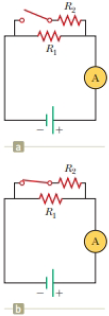
With the switch in the circuit of Figure 27.6a open, there is no current in R2. There is current in R1, however, and it is measured with the ammeter at the right side of the circuit. If the switch is closed (Fig. 27.6b), there is current in R2. What happens to the reading on the ammeter when the switch is closed? (a) The reading increases. (b) The reading decreases. (c) The reading does not change.
Figure 27.6 (Quick Quiz 27.3) What happens when the switch is closed?
Expert Solution & Answer

Trending nowThis is a popular solution!

Students have asked these similar questions
In the accompanying figure, the rails, connecting end piece, and rod all have a resistance per unit length of 2.0 Ω/cm. The rod moves to the left at v = 3.0 m/s. If B = 0.75 T everywhere in the region, what is the current in the circuit (a) when a = 8.0 cm? (b) when a = 5.0 cm? Specify also the sense of the current flow.
What is the current flowing through the battery immediately after the switch is closed and through the battery a long time after the switch has been closed? Use the following data: EMF = 14.5 V, R1 = 90.0 Ω, R2 = 10.0 Ω, L = 28.0 mH.
A moving coil ammeter gives a full scale deflection for a current i = 60 mA and its coil has a resistance RC = 0.5 Ω. It is provided with a multiplier resistance Rm = 2.5 Ω added in series.
What is the full scale deflection in volts of this modified ammeter?
Select one:
a. 30 mV
b. 24 mV
c. 150 mV
d. 180 mV
Chapter 28 Solutions
Physics for Scientists and Engineers, Technology Update (No access codes included)
Ch. 28 - To maximize the percentage of the power from the...Ch. 28 - With the switch in the circuit of Figure 27.4a...Ch. 28 - With the switch in the circuit of Figure 27.6a...Ch. 28 - Prob. 28.4QQCh. 28 - Consider the circuit in Figure 27.17 and assume...Ch. 28 - Is a circuit breaker wired (a) in series with the...Ch. 28 - A battery has some internal resistance. (i) Clan...Ch. 28 - The terminals of a battery are connected across...Ch. 28 - When operating on a 120-V circuit, an electric...Ch. 28 - If the terminals of a battery with zero internal...
Ch. 28 - Prob. 28.6OQCh. 28 - What is the time constant of the circuit shown in...Ch. 28 - When resistors with different resistances are...Ch. 28 - When resistors with different resistances are...Ch. 28 - The terminals of a battery are connected across...Ch. 28 - Are the two headlights of a car wired (a) in...Ch. 28 - In the circuit shown in Figure OQ28.12, each...Ch. 28 - Prob. 28.13OQCh. 28 - A circuit consists of three identical lamps...Ch. 28 - A series circuit consists of three identical lamps...Ch. 28 - Suppose a parachutist lands on a high-voltage wire...Ch. 28 - A student claims that the second of two lightbulbs...Ch. 28 - Why is ii possible for a bird to sit on a...Ch. 28 - Given three lightbulbs and a battery, sketch as...Ch. 28 - Prob. 28.5CQCh. 28 - Referring to Figure CQ28.6, describe what happens...Ch. 28 - Prob. 28.7CQCh. 28 - (a) What advantage does 120-V operation offer over...Ch. 28 - Prob. 28.9CQCh. 28 - Prob. 28.10CQCh. 28 - A battery has an emf of 15.0 V. The terminal...Ch. 28 - Two 1.50-V batterieswith their positive terminals...Ch. 28 - An automobile battery has an emf of 12.6 V and 171...Ch. 28 - As in Example 27.2, consider a power supply with...Ch. 28 - Three 100- resistors are connected as shown in...Ch. 28 - Prob. 28.6PCh. 28 - What is the equivalent resistance of the...Ch. 28 - Consider the two circuits shown in Figure P27.5 in...Ch. 28 - Consider the circuit shown in Figure P28.9. Find...Ch. 28 - (a) You need a 45- resistor, but the stockroom has...Ch. 28 - A battery with = 6.00 V and no internal...Ch. 28 - A battery with emf and no internal resistance...Ch. 28 - (a) Kind the equivalent resistance between points...Ch. 28 - (a) When the switch S in the circuit of Figure...Ch. 28 - Prob. 28.15PCh. 28 - Four resistors are connected to a battery as shown...Ch. 28 - Consider die combination of resistors shown in...Ch. 28 - For the purpose of measuring the electric...Ch. 28 - Calculate the power delivered to each resistor in...Ch. 28 - Why is the following situation impossible? A...Ch. 28 - Consider the circuit shown in Figure P28.21 on...Ch. 28 - In Figure P28.22, show how to add just enough...Ch. 28 - The circuit shown in Figure P27.17 is connected...Ch. 28 - For the circuit shown in Figure P28.24, calculate...Ch. 28 - What are the expected readings of (a) the ideal...Ch. 28 - The following equations describe an electric...Ch. 28 - Taking R = 1.00 k and = 250 V in Figure P27.19,...Ch. 28 - You have a faculty position at a community college...Ch. 28 - The ammeter shown in Figure P28.29 reads 2.00 A....Ch. 28 - In the circuit of Figure P28.30, determine (a) the...Ch. 28 - Using Kirchhoffs rules, (a) find (he current in...Ch. 28 - In the circuit of Figure P27.20, the current I1 =...Ch. 28 - In Figure P28.33, find (a) the current in each...Ch. 28 - For the circuit shown in Figure P27.22, we wish to...Ch. 28 - Find the potential difference across each resistor...Ch. 28 - (a) Can the circuit shown in Figure P27.21 be...Ch. 28 - An uncharged capacitor and a resistor are...Ch. 28 - Consider a series RC circuit as in Figure P28.38...Ch. 28 - A 2.00-nF capacitor with an initial charge of 5.10...Ch. 28 - A 10.0-F capacitor is charged by a 10.0-V battery...Ch. 28 - In the circuit of Figure P27.25, the switch S has...Ch. 28 - In the circuit of Figure P27.25, the switch S has...Ch. 28 - The circuit in Figure P28.43 has been connected...Ch. 28 - Show that the integral 0e2t/RCdtin Example 27.11...Ch. 28 - A charged capacitor is connected to a resistor and...Ch. 28 - Prob. 28.46PCh. 28 - Prob. 28.47PCh. 28 - Turn on your desk lamp. Pick up the cord, with...Ch. 28 - Assume you have a battery of emf and three...Ch. 28 - Find the equivalent resistance between points a...Ch. 28 - Four 1.50-V AA batteries in series are used to...Ch. 28 - Four resistors are connected in parallel across a...Ch. 28 - The circuit in Figure P27.35 has been connected...Ch. 28 - The circuit in Figure P27.34a consists of three...Ch. 28 - For the circuit shown in Figure P28.55. the ideal...Ch. 28 - The resistance between terminals a and b in Figure...Ch. 28 - (a) Calculate the potential difference between...Ch. 28 - Why is the following situation impossible? A...Ch. 28 - A rechargeable battery has an emf of 13.2 V and an...Ch. 28 - Find (a) the equivalent resistance of the circuit...Ch. 28 - When two unknown resistors are connected in series...Ch. 28 - When two unknown resistors are connected in series...Ch. 28 - The- pair of capacitors in Figure P28.63 are fully...Ch. 28 - A power supply has an open-circuit voltage of 40.0...Ch. 28 - The circuit in Figure P27.41 contains two...Ch. 28 - Two resistors R1 and R2 are in parallel with each...Ch. 28 - Prob. 28.67APCh. 28 - A battery is used to charge a capacitor through a...Ch. 28 - A young man owns a canister vacuum cleaner marked...Ch. 28 - (a) Determine the equilibrium charge on the...Ch. 28 - Switch S shown in Figure P28.71 has been closed...Ch. 28 - Three identical 60.0-W, 120-V lightbulbs are...Ch. 28 - A regular tetrahedron is a pyramid with a...Ch. 28 - An ideal voltmeter connected across a certain...Ch. 28 - In Figure P27.47, suppose the switch has been...Ch. 28 - Figure P27.48 shows a circuit model for the...Ch. 28 - The student engineer of a campus radio station...Ch. 28 - The circuit shown in Figure P28.78 is set up in...Ch. 28 - An electric teakettle has a multiposition switch...Ch. 28 - A voltage V is applied to a series configuration...Ch. 28 - In places such as hospital operating rooms or...Ch. 28 - The switch in Figure P27.51a closes when Vc23Vand...Ch. 28 - The resistor R in Figure P28.83 receives 20.0 W of...
Knowledge Booster


Learn more about
Need a deep-dive on the concept behind this application? Look no further. Learn more about this topic, physics and related others by exploring similar questions and additional content below.Similar questions
- Consider the RL circuit in the figure with R=10.00 Ω, L1=1.80 H, L2=3.90 H, and V=5.0 V. At time t=0, the switch is closed to connect the circuit to a constant emf. How long (in seconds) does it take for the current to reach a value of Imax/2.71828 of its maximum value, where Imax is the maximum current through the circuit?arrow_forwardThe capacitor in the figure below is uncharged for t < 0. If = 8.02 V, R = 58.9 Ω, and C = 4.00 µF, use Kirchhoff's loop rule to find the current (in A) through the resistor at the following times. The circuit is a rectangular loop. The bottom side of the loop has a battery labeled emf ℰ, oriented with the positive terminal to the right of the negative terminal. The right side has a resistor R. The top side contains an open switch S. The left side has a capacitor C. HINT (a) t = 0, when the switch is closed A (b) t = ?, one time constant after the switch is closed Aarrow_forwardAfter being closed for a long time, the switch S in the circuit shown in the figure below is thrown open at t = 0. In the circuit, E= 24.0 V, RA = 3.90 kΩ, RB = 7.20 kΩ, and L = 646 mH.arrow_forward
- In the circuit below, it is known that R1 = 10 kΩ, R2 = 15 kΩ, and C = 0.4 μF, and a battery with an Emf of 20 Volts. Initially, the connector (switch) is connected for a long time until it reaches a steady state. Then the switch is disconnected/opened at t = 0. What is the current flowing in resistor 2 at t = 4 ms?arrow_forwardIf the battery in the circuit below is 7.16V, resistor R1=331.15ΩΩ, and resistor R2=51.49ΩΩ, what is the magnitude of the current flowing through the circuit? Please give your answer in units of milli-Amps (mA).arrow_forwardIn the circuit below, the switch has been in the open position for a long time. At t=0, the switch is turned on. If the current at time t=3.3 ms reaches half of its maximum value, L=68 mH, and ℰ=17 V, find:the time constant τ= ms,the resistance R= Ω,the maximum value of the current, Imax= A.If the switch is open again, after what time, the current will reach the half of its value?t1/2= ms.arrow_forward
- When the switch is open in Figure 18.8, power Po is delivered to the resistor R1. When the switch is closed, which of the following is true about the power Pc delivered to R1? (Neglect the internal resistance of the battery.) (a) Pc Po (b) Pc = Po (c) Pc Po Figure 18.8 (Quick Quizzes 18.5 and 18.6)arrow_forwardIn the circuit of Figure P27.25, the switch S has been open for a long time. It is then suddenly closed. Take = 10.0 V, R1 = 50.0 k, R2 = 100 k, and C = 10.0 F. Determine the time constant (a) before the switch is closed and (b) after the switch is closed. (c) Let the switch be closed at t = 0. Determine the current in the switch as a function of time. Figure P27.25 Problems 25 and 26.arrow_forwardThe switch is closed in Figure 18.20. After a long time compared with the time constant, of the circuit, what will the current be in the 2- resistor? (a) 4 A (b) 3 A (c) 2 A (d) 1 A (c) More information is needed. Figure 18.20 (Quick Quiz 18.9)arrow_forward
- In the circuit of Figure P27.25, the switch S has been open for a long time. It is then suddenly closed. Determine the time constant (a) before the switch is closed and (b) after the switch is closed. (c) Let the switch be closed at t = 0. Determine the current in the switch as a function of time. Figure P27.25 Problems 25 and 26.arrow_forwardFind the direction of the current in the resistor shown in Figure P20.16 (a) at the instant the switch is closed, (b) after the switch has been closed for several minutes, and (c) at the instant the switch is opened. Figure P20.16arrow_forwardThe switch is closed in Figure 18.20. After a long time compared with the time constant, of the circuit, what will the current be in the 2- resistor? (a) 4 A (b) 3 A (c) 2 A (d) 1 A (c) More information is needed. Figure 18.20 (Quick Quiz 18.9)arrow_forward
arrow_back_ios
SEE MORE QUESTIONS
arrow_forward_ios
Recommended textbooks for you
 Principles of Physics: A Calculus-Based TextPhysicsISBN:9781133104261Author:Raymond A. Serway, John W. JewettPublisher:Cengage Learning
 Physics for Scientists and EngineersPhysicsISBN:9781337553278Author:Raymond A. Serway, John W. JewettPublisher:Cengage Learning
 Physics for Scientists and Engineers with Modern ...PhysicsISBN:9781337553292Author:Raymond A. Serway, John W. JewettPublisher:Cengage Learning
 College PhysicsPhysicsISBN:9781285737027Author:Raymond A. Serway, Chris VuillePublisher:Cengage Learning
 College PhysicsPhysicsISBN:9781305952300Author:Raymond A. Serway, Chris VuillePublisher:Cengage Learning
Principles of Physics: A Calculus-Based Text
Physics
ISBN:9781133104261
Author:Raymond A. Serway, John W. Jewett
Publisher:Cengage Learning
Physics for Scientists and Engineers
Physics
ISBN:9781337553278
Author:Raymond A. Serway, John W. Jewett
Publisher:Cengage Learning
Physics for Scientists and Engineers with Modern ...
Physics
ISBN:9781337553292
Author:Raymond A. Serway, John W. Jewett
Publisher:Cengage Learning
College Physics
Physics
ISBN:9781285737027
Author:Raymond A. Serway, Chris Vuille
Publisher:Cengage Learning
College Physics
Physics
ISBN:9781305952300
Author:Raymond A. Serway, Chris Vuille
Publisher:Cengage Learning
DC Series circuits explained - The basics working principle; Author: The Engineering Mindset;https://www.youtube.com/watch?v=VV6tZ3Aqfuc;License: Standard YouTube License, CC-BY