
Physics for Scientists and Engineers, Technology Update (No access codes included)
9th Edition
ISBN: 9781305116399
Author: Raymond A. Serway, John W. Jewett
Publisher: Cengage Learning
expand_more
expand_more
format_list_bulleted
Videos
Textbook Question
thumb_up100%
Chapter 28, Problem 28.6CQ
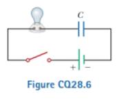
Referring to Figure CQ28.6, describe what happens to the lightbulb after the switch is closed. Assume the capacitor has a large capacitance and is initially uncharged. Also assume the light illuminates when connected directly across the battery terminals.
Expert Solution & Answer

Trending nowThis is a popular solution!

Students have asked these similar questions
A 10 MΩ resistor is connected in series with a 1.0 μF capacitor and a battery with emf 12.0 V. Before the switch is closed at time t=0,the capacitor is uncharged. What fraction of the final charge Qf is on the capacitor at t=10s?
When an initially uncharged capacitor is charged through a 25-k resistor by a 75-V dc ideal power source, it takes 0.30 ms for the capacitor to reach 50% of its maximum charge? What is the capacitance of this capacitor?
Switch S in in the figure is closed at time t = 0, to begin charging an initially uncharged capacitor of capacitance C = 17.2 μF through a resistor of resistance R = 21.2 Ω. At what time is the potential across the capacitor equal to that across the resistor?
Chapter 28 Solutions
Physics for Scientists and Engineers, Technology Update (No access codes included)
Ch. 28 - To maximize the percentage of the power from the...Ch. 28 - With the switch in the circuit of Figure 27.4a...Ch. 28 - With the switch in the circuit of Figure 27.6a...Ch. 28 - Prob. 28.4QQCh. 28 - Consider the circuit in Figure 27.17 and assume...Ch. 28 - Is a circuit breaker wired (a) in series with the...Ch. 28 - A battery has some internal resistance. (i) Clan...Ch. 28 - The terminals of a battery are connected across...Ch. 28 - When operating on a 120-V circuit, an electric...Ch. 28 - If the terminals of a battery with zero internal...
Ch. 28 - Prob. 28.6OQCh. 28 - What is the time constant of the circuit shown in...Ch. 28 - When resistors with different resistances are...Ch. 28 - When resistors with different resistances are...Ch. 28 - The terminals of a battery are connected across...Ch. 28 - Are the two headlights of a car wired (a) in...Ch. 28 - In the circuit shown in Figure OQ28.12, each...Ch. 28 - Prob. 28.13OQCh. 28 - A circuit consists of three identical lamps...Ch. 28 - A series circuit consists of three identical lamps...Ch. 28 - Suppose a parachutist lands on a high-voltage wire...Ch. 28 - A student claims that the second of two lightbulbs...Ch. 28 - Why is ii possible for a bird to sit on a...Ch. 28 - Given three lightbulbs and a battery, sketch as...Ch. 28 - Prob. 28.5CQCh. 28 - Referring to Figure CQ28.6, describe what happens...Ch. 28 - Prob. 28.7CQCh. 28 - (a) What advantage does 120-V operation offer over...Ch. 28 - Prob. 28.9CQCh. 28 - Prob. 28.10CQCh. 28 - A battery has an emf of 15.0 V. The terminal...Ch. 28 - Two 1.50-V batterieswith their positive terminals...Ch. 28 - An automobile battery has an emf of 12.6 V and 171...Ch. 28 - As in Example 27.2, consider a power supply with...Ch. 28 - Three 100- resistors are connected as shown in...Ch. 28 - Prob. 28.6PCh. 28 - What is the equivalent resistance of the...Ch. 28 - Consider the two circuits shown in Figure P27.5 in...Ch. 28 - Consider the circuit shown in Figure P28.9. Find...Ch. 28 - (a) You need a 45- resistor, but the stockroom has...Ch. 28 - A battery with = 6.00 V and no internal...Ch. 28 - A battery with emf and no internal resistance...Ch. 28 - (a) Kind the equivalent resistance between points...Ch. 28 - (a) When the switch S in the circuit of Figure...Ch. 28 - Prob. 28.15PCh. 28 - Four resistors are connected to a battery as shown...Ch. 28 - Consider die combination of resistors shown in...Ch. 28 - For the purpose of measuring the electric...Ch. 28 - Calculate the power delivered to each resistor in...Ch. 28 - Why is the following situation impossible? A...Ch. 28 - Consider the circuit shown in Figure P28.21 on...Ch. 28 - In Figure P28.22, show how to add just enough...Ch. 28 - The circuit shown in Figure P27.17 is connected...Ch. 28 - For the circuit shown in Figure P28.24, calculate...Ch. 28 - What are the expected readings of (a) the ideal...Ch. 28 - The following equations describe an electric...Ch. 28 - Taking R = 1.00 k and = 250 V in Figure P27.19,...Ch. 28 - You have a faculty position at a community college...Ch. 28 - The ammeter shown in Figure P28.29 reads 2.00 A....Ch. 28 - In the circuit of Figure P28.30, determine (a) the...Ch. 28 - Using Kirchhoffs rules, (a) find (he current in...Ch. 28 - In the circuit of Figure P27.20, the current I1 =...Ch. 28 - In Figure P28.33, find (a) the current in each...Ch. 28 - For the circuit shown in Figure P27.22, we wish to...Ch. 28 - Find the potential difference across each resistor...Ch. 28 - (a) Can the circuit shown in Figure P27.21 be...Ch. 28 - An uncharged capacitor and a resistor are...Ch. 28 - Consider a series RC circuit as in Figure P28.38...Ch. 28 - A 2.00-nF capacitor with an initial charge of 5.10...Ch. 28 - A 10.0-F capacitor is charged by a 10.0-V battery...Ch. 28 - In the circuit of Figure P27.25, the switch S has...Ch. 28 - In the circuit of Figure P27.25, the switch S has...Ch. 28 - The circuit in Figure P28.43 has been connected...Ch. 28 - Show that the integral 0e2t/RCdtin Example 27.11...Ch. 28 - A charged capacitor is connected to a resistor and...Ch. 28 - Prob. 28.46PCh. 28 - Prob. 28.47PCh. 28 - Turn on your desk lamp. Pick up the cord, with...Ch. 28 - Assume you have a battery of emf and three...Ch. 28 - Find the equivalent resistance between points a...Ch. 28 - Four 1.50-V AA batteries in series are used to...Ch. 28 - Four resistors are connected in parallel across a...Ch. 28 - The circuit in Figure P27.35 has been connected...Ch. 28 - The circuit in Figure P27.34a consists of three...Ch. 28 - For the circuit shown in Figure P28.55. the ideal...Ch. 28 - The resistance between terminals a and b in Figure...Ch. 28 - (a) Calculate the potential difference between...Ch. 28 - Why is the following situation impossible? A...Ch. 28 - A rechargeable battery has an emf of 13.2 V and an...Ch. 28 - Find (a) the equivalent resistance of the circuit...Ch. 28 - When two unknown resistors are connected in series...Ch. 28 - When two unknown resistors are connected in series...Ch. 28 - The- pair of capacitors in Figure P28.63 are fully...Ch. 28 - A power supply has an open-circuit voltage of 40.0...Ch. 28 - The circuit in Figure P27.41 contains two...Ch. 28 - Two resistors R1 and R2 are in parallel with each...Ch. 28 - Prob. 28.67APCh. 28 - A battery is used to charge a capacitor through a...Ch. 28 - A young man owns a canister vacuum cleaner marked...Ch. 28 - (a) Determine the equilibrium charge on the...Ch. 28 - Switch S shown in Figure P28.71 has been closed...Ch. 28 - Three identical 60.0-W, 120-V lightbulbs are...Ch. 28 - A regular tetrahedron is a pyramid with a...Ch. 28 - An ideal voltmeter connected across a certain...Ch. 28 - In Figure P27.47, suppose the switch has been...Ch. 28 - Figure P27.48 shows a circuit model for the...Ch. 28 - The student engineer of a campus radio station...Ch. 28 - The circuit shown in Figure P28.78 is set up in...Ch. 28 - An electric teakettle has a multiposition switch...Ch. 28 - A voltage V is applied to a series configuration...Ch. 28 - In places such as hospital operating rooms or...Ch. 28 - The switch in Figure P27.51a closes when Vc23Vand...Ch. 28 - The resistor R in Figure P28.83 receives 20.0 W of...
Knowledge Booster


Learn more about
Need a deep-dive on the concept behind this application? Look no further. Learn more about this topic, physics and related others by exploring similar questions and additional content below.Similar questions
- Referring to Figure CQ21.4, describe what happens to the light-bulb after the switch is closed. Assume the capacitor has a large capacitance and is initially uncharged. Also assume the light illuminates when connected directly across the battery terminals.arrow_forwardFigure P29.84 shows a circuit that consists of two identical emf devices. If R1 = R2 = R and the switch is closed, find an expression (in terms of R and ) for the current I that is in the branch from point a to b.arrow_forwardA parallel-plate capacitor with a plate separation d has acapacitance C0 in the absence of a dielectric. A slab of dielectricmaterial of dielectric constant k and thickness d/ 3 is then inserted between the plates as in Figure P16.61a. Show thatthe capacitance of this partially filled capacitor is given byarrow_forward
- When the switch S1 is closed and S2 is open, the capacitor C charges through the resistor R1 = 2.1x10⁵ Ω. When theswitch S1 is open while S2 is closed, the capacitor discharges current through the R2= 1x10³ Ω.1) If the capacitor is initially uncharged with C = 9 μF and ε = 750 V, R1 = 2.1x10⁵ Ω, find the voltage of capacitor in 0.25 swhen the switch S1 is closed and S2 is open.2) After the capacitor is fully charged, the switch S1 is open while S2 is closed, if R2 = 1x10³Ω, calculate the voltage (inV) across the capacitor after 6.2 ms.arrow_forwardIn Figure P29.81, N real batteries, each with an emf and internal resistance r, are connected in a closed ring. A resistor R can be connected across any two points of this ring, causing there to be n real batteries in one branch and N n resistors in the other branch. Find an expression for the current through the resistor R in this case.arrow_forwardFigure P18.37 shows a simplified model of a cardiac defibrillator, a device used to patients in ventricular fibrillation. When the switch S is toggled to the left, the capacitor C charges through the resistor R .When the switch is toggled to the right, the capacitor discharges current through the patients torso, modeled as the resistor Rtorso, allowing the hearts normal rhythm to be reestablished. (a) If the capacitor is initially uncharged with C = 8.00 F and = 1250 V, find the value of R required to charge the capacitor to a voltage of 775 V in 1.50 s. (b) If the capacitor is then discharged across the patients torso with, Rtorso = 1250 , calculate the voltage across the capacitor after 5.00 ms. Figure P18.37arrow_forward
- (a) What is the average power output of a heart defibrillator that dissipates 400 J of energy in 10.0 ms? (b) Considering the high-power output, why doesn’t the defibrillator produce serious bums?arrow_forwardIn the circuit of Figure P27.25, the switch S has been open for a long time. It is then suddenly closed. Determine the time constant (a) before the switch is closed and (b) after the switch is closed. (c) Let the switch be closed at t = 0. Determine the current in the switch as a function of time. Figure P27.25 Problems 25 and 26.arrow_forwardThe student engineer of a campus radio station wishes to verify the effectiveness of the lightning rod on the antenna mast (Fig. P27.49). The unknown resistance Rx is between points C and E. Point E is a true ground, but it is inaccessible for direct measurement because this stratum is several meters below the Earths surface. Two identical rods are driven into the ground at A and B, introducing an unknown resistance Ry. The procedure is as follows. Measure resistance R1 between points A and B, then connect A and B with a heavy conducting wire and measure resistance R2 between points A and C. (a) Derive an equation for Rx in terms of the observable resistances, R1, and R2. (b) A satisfactory ground resistance would Rx 2.00 . Is the grounding of the station adequate if measurements give R1 = 13.0 and R2 = 6.00 ? Explain. Figure P27.49arrow_forward
- A Pairs of parallel wires or coaxial cables are two conductors separated by an insulator, so they have a capacitance. For a given cable, the capacitance is independent of the length if the cable is very long. A typical circuit model of a cable is shown in Figure P27.87. It is called a lumped-parameter model and represents how a unit length of the cable behaves. Find the equivalent capacitance of a. one unit length (Fig. P27.87A), b. two unit lengths (Fig. P27.87B), and c. an infinite number of unit lengths (Fig. P27.87C). Hint: For the infinite number of units, adding one more unit at the beginning does not change the equivalent capacitance.arrow_forwardIn the RC circuit shown in Figure P29.78, an ideal battery with emf and internal resistance r is connected to capacitor C. The switch S is initially open and the capacitor is uncharged. At t = 0, the switch is closed. a. Determine the charge q on the capacitor at time t. b. Find the current in the branch be at time t. What is the current as t goes to infinity?arrow_forwardFigure P18.37 shows a simplified model of a cardiac defibrillator, a device used to patients in ventricular fibrillation. When the switch S is toggled to the left, the capacitor C charges through the resistor R .When the switch is toggled to the right, the capacitor discharges current through the patients torso, modeled as the resistor Rtorso, allowing the hearts normal rhythm to be reestablished. (a) If the capacitor is initially uncharged with C = 8.00 F and = 1250 V, find the value of R required to charge the capacitor to a voltage of 775 V in 1.50 s. (b) If the capacitor is then discharged across the patients torso with, Rtorso = 1250 , calculate the voltage across the capacitor after 5.00 ms. Figure P18.37arrow_forward
arrow_back_ios
arrow_forward_ios
Recommended textbooks for you
 Physics for Scientists and Engineers, Technology ...PhysicsISBN:9781305116399Author:Raymond A. Serway, John W. JewettPublisher:Cengage Learning
 Principles of Physics: A Calculus-Based TextPhysicsISBN:9781133104261Author:Raymond A. Serway, John W. JewettPublisher:Cengage Learning
 Physics for Scientists and Engineers: Foundations...PhysicsISBN:9781133939146Author:Katz, Debora M.Publisher:Cengage Learning
 Physics for Scientists and Engineers with Modern ...PhysicsISBN:9781337553292Author:Raymond A. Serway, John W. JewettPublisher:Cengage Learning
 Physics for Scientists and EngineersPhysicsISBN:9781337553278Author:Raymond A. Serway, John W. JewettPublisher:Cengage Learning
 College PhysicsPhysicsISBN:9781305952300Author:Raymond A. Serway, Chris VuillePublisher:Cengage Learning
Physics for Scientists and Engineers, Technology ...
Physics
ISBN:9781305116399
Author:Raymond A. Serway, John W. Jewett
Publisher:Cengage Learning
Principles of Physics: A Calculus-Based Text
Physics
ISBN:9781133104261
Author:Raymond A. Serway, John W. Jewett
Publisher:Cengage Learning
Physics for Scientists and Engineers: Foundations...
Physics
ISBN:9781133939146
Author:Katz, Debora M.
Publisher:Cengage Learning
Physics for Scientists and Engineers with Modern ...
Physics
ISBN:9781337553292
Author:Raymond A. Serway, John W. Jewett
Publisher:Cengage Learning
Physics for Scientists and Engineers
Physics
ISBN:9781337553278
Author:Raymond A. Serway, John W. Jewett
Publisher:Cengage Learning
College Physics
Physics
ISBN:9781305952300
Author:Raymond A. Serway, Chris Vuille
Publisher:Cengage Learning
DC Series circuits explained - The basics working principle; Author: The Engineering Mindset;https://www.youtube.com/watch?v=VV6tZ3Aqfuc;License: Standard YouTube License, CC-BY