
Concept explainers
Videos
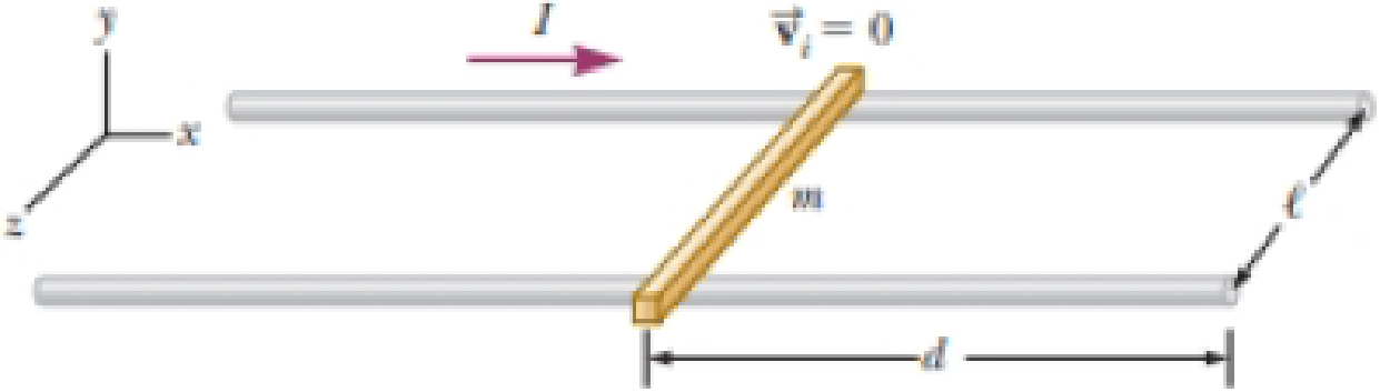
Review. Rail guns have been suggested for launching projectiles into space without chemical rockets. A tabletop model rail gun (Fig. P29.42) consists of two long, parallel, horizontal rails ℓ = 3.50 cm apart, bridged by a bar of mass m = 3.00 g that is free to slide without friction. The rails and bar have low electric resistance, and the current is limited to a constant I = 24.0 A by a power supply that is far to the left of the figure, so it has no magnetic effect on the bar. Figure P29.42 shows the bar at rest at the midpoint of the rails at the moment the current is established. We wish to find the speed with which the bar leaves the rails after being released from the midpoint of the rails. (a) Find the magnitude of the magnetic field at a distance of 1.75 cm from a single long wire carrying a current of 2.40 A. (b) For purposes of evaluating the magnetic field, model the rails as infinitely long. Using the result of part (a), find the magnitude and direction of the magnetic field at the midpoint of the bar. (c) Argue that this value of the field will be the same at all positions of the bar to the right of the midpoint of the rails. At other points along the bar, the field is in the same direction as at the midpoint, but is larger in magnitude. Assume the average effective magnetic field along the bar is five times larger than the field at the midpoint. With this assumption, find (d) the magnitude and (e) the direction of the force on the bar. (f) Is the bar properly modeled as a particle under constant acceleration? (g) Find the velocity of the bar after it has traveled a distance d = 130 cm to the end of the rails.
Figure P29.42
(a)
The magnitude of the magnetic field at a distance of
Answer to Problem 42AP
The magnitude of the magnetic field at a distance of
Explanation of Solution
Given info: The length of the rails is
Formula to calculate the magnetic field is
Here,
Substitute
Conclusion:
Therefore, the magnitude of the magnetic field at a distance of
(b)
The magnitude and direction of the magnetic field at the mid-point of the bar.
Answer to Problem 42AP
The magnitude of the magnetic field at the mid-point of the bar is
Explanation of Solution
Given info: The length of the rails is
The diagram that represents the given situation is shown below.
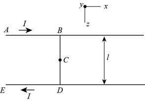
Figure (I)
Since the current is diverted through the bar, only half of each rails carries currents, so the field produce by each rail is half of the infinitely long wire produces.
Write the expression for the magnetic field produce by conductor AB at point C is,
Substitute
Write the expression for the magnetic field produce by conductor DE at point C is,
Substitute
Formula to calculate the total magnetic field at point C is,
Substitute
Conclusion:
Therefore, the magnitude of the magnetic field at the mid-point of the bar is
(c)
The reason that the value of magnetic field will be same at all position of the bar to the right of the midpoint of the rails.
Answer to Problem 42AP
The rails are very long so the location of the bar does not depend upon the length of the rail to the right side.
Explanation of Solution
Given info: The length of the rails is
The assumption makes that the rails are infinitely long so, the length of the rail to the right of the bar does not depend upon the location of the bar. Hence the magnetic field will be same at all position of the bar to the right of the midpoint of the rails.
Conclusion:
Therefore, due to infinite length of the rails makes the field same at all position of the midpoint of the bar.
(d)
The magnitude of the force on the bar.
Answer to Problem 42AP
The magnitude of the force on the bar is
Explanation of Solution
Given info: The length of the rails is
Formula to calculate the force on the bar is,
Here,
Substitute
Conclusion:
Therefore, the magnitude of the force on the bar is
(e)
The direction of the force on the bar.
Answer to Problem 42AP
The direction of the force on the bar is in positive x-direction.
Explanation of Solution
Given info: The length of the rails is
The force vector on the bar is
Conclusion:
Therefore, the direction of the force on the bar is in positive x-direction.
(f)
Whether the bar is properly modeled as a particle under constant acceleration.
Answer to Problem 42AP
Yes, the bar will move with constant acceleration of magnitude
Explanation of Solution
Given info: The length of the rails is
The length of the bar, value of current and field producer is constant so, the force exerted on the bar is constant that gives uniform acceleration of the bar.
Formula to calculate the acceleration of the bar is,
Substitute
Conclusion:
Therefore, the bar will move with constant acceleration of magnitude
(g)
The velocity of the bar.
Answer to Problem 42AP
The velocity of the bar is
Explanation of Solution
Given info: The length of the rails is
Formula to calculate the velocity of the bar is,
Here,
Substitute
Conclusion:
Therefore, the velocity of the bar is
Want to see more full solutions like this?
Chapter 29 Solutions
Physics for Scientists and Engineers with Modern Physics
Additional Science Textbook Solutions
University Physics (14th Edition)
Introduction to Electrodynamics
The Cosmic Perspective
Physics for Scientists and Engineers, Technology Update (No access codes included)
Physical Science
Physics for Scientists and Engineers: A Strategic Approach, Vol. 1 (Chs 1-21) (4th Edition)


- Review. In studies of the possibility of migrating birds using the Earths magnetic field for navigation, birds have been fitted with coils as caps and collars as shown in Figure P22.39. (a) If the identical coils have radii of 1.20 cm and are 2.20 cm apart, with 50 turns of wire apiece, what current should they both carry to produce a magnetic field of 4.50 105 T halfway between them? (b) If the resistance of each coil is 210 V, what voltage should the battery supplying each coil have? (c) What power is delivered to each coil? Figure P22.39arrow_forwardA piece of insulated wire is shaped into a figure eight as shown in Figure P23.12. For simplicity, model the two halves of the figure eight as circles. The radius of the upper circle is 5.00 cm and that of the lower circle is 9.00 cm. The wire has a uniform resistance per unit length of 3.00 Ω/m. A uniform magnetic field is applied perpendicular to the plane of the two circles, in the direction shown. The magnetic field is increasing at a constant rate of 2.00 T/s. Find (a) the magnitude and (b) the direction of the induced current in the wire. Figure P23.12arrow_forwardReview. The use of superconductors has been proposed for power transmission lines. A single coaxial cable (Fig. P23.73) could carry a power of 1.00 103 MW (the output of a large power plant) at 200 kV, DC, over a distance of 1.00 103 km without loss. An inner wire of radius a = 2.00 cm, made from the superconductor Nb3Sn, carries the current I in one direction. A surrounding superconducting cylinder of radius b = 5.00 cm would carry the return current I. In such a system, what is the magnetic field (a) at the surface of the inner conductor and (b) at the inner surface of the outer conductor? (c) How much energy would be stored in the magnetic field in the space between the conductors in a 1.00 103 km superconducting line? (d) What is the pressure exerted on the outer conductor due to the current in the inner conductor? Figure. P23.73arrow_forward
- A conducting rod of length ℓ moves on two horizontal, frictionless rails as shown inFigure P31.26. If a constant force of 1.00 N moves the bar at 2.00 m/s through amagnetic field B that is directed into the page (a) what is the current through the 8.00-Ω resistor R? (b) What is the rate at which energy is delivered to the resistor? (c) Whatis the mechanical power delivered by the force Fapp?arrow_forwardIn Figure P30.38, the rolling axle, 1.50 m long, is pushed along horizontal rails at a constant speed v = 3.00 m/s. A resistor R = 0.400 is connected to the rails at points a and b, directly opposite each other. The wheels make good electrical contact with the rails, so the axle, rails, and R form a closed-loop circuit. The only significant resistance in the circuit is R. A uniform magnetic field B = 0.080 0 T is vertically downward. (a) Find the induced current I in the resistor. (b) What horizontal force F is required to keep the axle rolling at constant speed? (c) Which end of the resistor, a or b, is at the higher electric potential? (d) What If? After the axle rolls past the resistor, does the current in R reverse direction? Explain your answer. Figure P30.38arrow_forwardA rectangular conducting loop is placed near a long wire carrying a current I as shown in Figure OQ23.5. If I decreases in time, what can be said of the current induced in the loop? (a) The direction of the current depends on the size of the loop. (b) The current is clockwise. (c) The current is counterclockwise. (d) The current is zero. (e) Nothing can be said about the current in the loop without more information.arrow_forward
- Mass m = 1.00 kg is suspended vertically at rest by an insulating string connected to a circuit partially immersed in a magnetic field as in Figure P19.30. The magnetic field has magnitude Bin = 2.00 T and the length = 0.500 m. (a) Find the current I. (b) If = 115 V, find the required resistance R. Figure P19.30arrow_forwardThe homopolar generator, also called the Faraday disk, is a low-voltage, high-current electric generator. It consists of a rotating conducting disk with one stationary brush (a sliding electrical contact) at its axle and another at a point on its circumference as shown in Figure P23.21. A uniform magnetic field is applied perpendicular to the plane of the disk. Assume the field is 0.900 T, the angular speed is 3.20 103 rev/min, and the radius of the disk is 0.400 m. Find the emf generated between the brushes. When superconducting coils are used to produce a large magnetic field, a homopolar generator can have a power output of several megawatts. Such a generator is useful, for example, in purifying metals by electrolysis. If a voltage is applied to the output terminals of the generator, it runs in reverse as a homopolar motor capable of providing great torque, useful in ship propulsion.arrow_forwardThe bar in Figure OQ23.10 moves on rails to the right with a velocity v, and a uniform, constant magnetic field is directed out of the page. Which of the following statements are correct? More than one statement may be correct. (a) The induced current in the loop is zero. (b) The induced current in the loop is clockwise. (c) The induced current in the loop is counterclockwise. (d) An external force is required to keep the bar moving at constant speed. (e) No force is required to keep the bar moving at constant speed.arrow_forward
- A wire carrying a current I is bent into the shape of an exponential spiral, r = e, from = 0 to = 2 as suggested in Figure P29.47. To complete a loop, the ends of the spiral are connected by a straight wire along the x axis. (a) The angle between a radial line and its tangent line at any point on a curve r = f() is related to the function by tan=rdr/d Use this fact to show that = /4. (b) Find the magnetic field at the origin. Figure P29.47arrow_forwardConsider the apparatus shown in Figure P30.32: a conducting bar is moved along two rails connected to an incandescent lightbulb. The whole system is immersed in a magnetic field of magnitude B = 0.400 T perpendicular and into the page. The distance between the horizontal rails is = 0.800 m. The resistance of the lightbulb is R = 48.0 , assumed to be constant. The bar and rails have negligible resistance. The bar is moved toward the right by a constant force of magnitude F = 0.600 N. We wish to find the maximum power delivered to the lightbulb. (a) Find an expression for the current in the lightbulb as a function of B, , R, and v, the speed of the bar. (b) When the maximum power is delivered to the lightbulb, what analysis model properly describes the moving bar? (c) Use the analysis model in part (b) to find a numerical value for the speed v of the bar when the maximum power is being delivered to the lightbulb. (d) Find the current in the lightbulb when maximum power is being delivered to it. (e) Using P = I2R, what is the maximum power delivered to the lightbulb? (f) What is the maximum mechanical input power delivered to the bar by the force F? (g) We have assumed the resistance of the lightbulb is constant. In reality, as the power delivered to the lightbulb increases, the filament temperature increases and the resistance increases. Does the speed found in part (c) change if the resistance increases and all other quantities are held constant? (h) If so, does the speed found in part (c) increase or decrease? If not, explain. (i) With the assumption that the resistance of the lightbulb increases as the current increases, does the power found in part (f) change? (j) If so, is the power found in part (f) larger or smaller? If not, explain. Figure P30.32arrow_forward
 Principles of Physics: A Calculus-Based TextPhysicsISBN:9781133104261Author:Raymond A. Serway, John W. JewettPublisher:Cengage Learning
 Physics for Scientists and Engineers with Modern ...PhysicsISBN:9781337553292Author:Raymond A. Serway, John W. JewettPublisher:Cengage Learning
 Physics for Scientists and EngineersPhysicsISBN:9781337553278Author:Raymond A. Serway, John W. JewettPublisher:Cengage Learning
 Physics for Scientists and Engineers, Technology ...PhysicsISBN:9781305116399Author:Raymond A. Serway, John W. JewettPublisher:Cengage Learning
 Physics for Scientists and Engineers: Foundations...PhysicsISBN:9781133939146Author:Katz, Debora M.Publisher:Cengage Learning
 College PhysicsPhysicsISBN:9781285737027Author:Raymond A. Serway, Chris VuillePublisher:Cengage Learning