
Videos
A steel pipe of 12-in. outer diameter is fabricated from ¼-in.-thick plate by welding along a helix that forms an angle of 45° with a plane parallel to the axis of the pipe. Knowing that the maximum allowable tensile stress in the weld is 12 ksi, determine the largest torque that can be applied to the pipe.
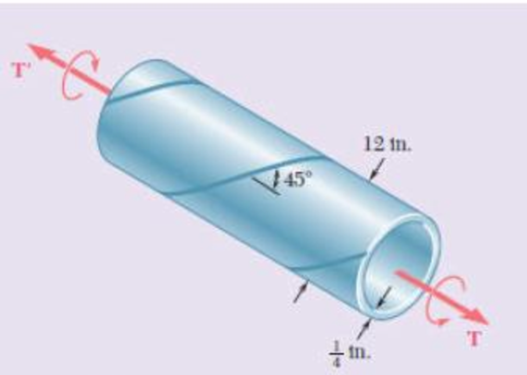
Fig. P3.151
Find the largest torque that can be applied to the pipe.
Answer to Problem 151RP
The largest torque that can be applied to the pipe is
Explanation of Solution
Given information:
The outer diameter of the steel pipe
The thickness of the steel pipe (t) is
The angle of the helix is
The maximum allowable tensile stress in the weld
Calculation:
Calculate the inner radius of the steel pipe
Substitute
Calculate the polar moment of inertia of steel pipe (J) as follows:
Here,
Substitute
The torsion formula for maximum shear stress in the solid shaft AB
Here, T is the applied internal torque.
Substitute
Therefore, the largest torque that can be applied to the pipe is
Want to see more full solutions like this?
Chapter 3 Solutions
MECHANICS OF MATERIALS


- A steel pipe of 400-mm outer diameter is fabricated from 10-mmthick plate by welding along a helix that forms an angle of 20° with a plane perpendicular to the axis of the pipe. Knowing that a 300-kN axial force P is applied to the pipe, determine the normal and shearing stresses in directions respectively normal and tangential to the weld.arrow_forwardEach of the three aluminum bars shown is to be twisted through an angle of 2.1°. Knowing that b = 30 mm, τall = 50 MPa, and G = 27 GPa, determine the shortest allowable length of each bar. Refer to Table 3.1. The shortest allowable length of bar (a) is mm. The shortest allowable length of bar (b) is mm. The shortest allowable length of bar (c) is mm.arrow_forwardA composite shaft shown, composed of a steel (G = 77 GPa) core inside an aluminum (G = 25 GPa) jacket, carries a torque, T = 10 kN-m. The shaft is designed such that the aluminum jacket will fail first upon the application of the torque. 1) If the allowable shear strength of aluminum is 45 MPa, determine the minimum thickness, t, of the aluminum jacket, that can carry the torque.2) What must be the minimum shear strength of steel such that the aluminum jacket will fail first?3) Determine the maximum angle of twist that can be applied to the shaft.arrow_forward
- Two steel plates are to be held together by means of 16-mm-diameter high-strength steel bolts fitting snugly inside cylindrical brass spacers. Knowing that the average normal stress must not exceed 205 MPa in the bolts and 132 MPa in the spacers, determine the outer diameter of the spacers that yields the most economical and safe design. The outer diameter of the spacers that yields the most economical and safe design is mm.arrow_forwardTwo solid cylindrical rods AB and BC are welded together at B and loaded as shown. Knowing that d1 = 50 mm and d2 = 30 mm, find the average normal stress at the midsection of (a) rod AB, (b) rod BC.arrow_forwardDetermine the diameter of the largest circular hole that can be punched into a sheet of polystyrene 6 mm thick, knowing that the force exerted by the punch is 45 kN and that a 55-MPa average shearing stress is required to cause the material to fail.arrow_forward
- Two steel plates are to be held together by means of 16-mm-diameter high-strength steel bolts fitting snugly inside cylindrical brass spacers.Knowing that the average normal stress must not exceed 200 MPa in the bolts and 130 MPa in the spacers, determine the outer diameter of the spacers that yields the most economical and safe design.arrow_forwardA fabric used in air-inflated structures is subjected to a biaxial loading that results in normal stresses ox = 18 ksi and oz = 24 ksi.Knowing that the properties of the fabric can be approximated as E = 12.6 x 10 psi and v = 0.34, determine the change in length of (a) side AB, (b) side BC, (c) diagonal AC.arrow_forwardA torque of magnitude T=12 kN·m is applied to the end of a tank containing compressed air under a pressure of 8 MPa. Knowing that the tank has a 180-mm inner diameter and a 12-mm wall thickness, determine the maximum normal stress and the maximum in-plane shearing stress in the tank.arrow_forward
- The composite shaft shown is to be twisted by applying a torque T at end A. Knowing that the modulus of rigidity is 77 GPa for the steel and 27 GPa for the aluminum, determine the largest angle through which end A can be rotated if the following allowable stresses are not be exceeded: τsteel= 60 MPa and τaluminum= 45 MPa.arrow_forwardThe composite shaft shown consists of a 0.2-in.-thick brass jacket (Gbrass= 5.6 × 10⁶ psi) bonded to a 1.2-in.-diameter steel core (Gsteel=11.2 × 10⁶ psi). Knowing that the shaft is being subjected to the torques shown, determine the largest angle through which it can be twisted if the following allowable stresses are not to be exceeded: τsteel=15 ksi and τbrass= 8 ksi.arrow_forwardThe steel pressure tank shown has a 750-mm inner diameter and a 9-mm wall thickness. Knowing that the butt-welded seams form an angle β= 50° with the longitudinal axis of the tank and that the gage pressure in the tank is 1.5 MPa, determine, (a) the normal stress per-pendicular to the weld, (b) the shearing stress parallel to the weld.arrow_forward
 Elements Of ElectromagneticsMechanical EngineeringISBN:9780190698614Author:Sadiku, Matthew N. O.Publisher:Oxford University Press
 Mechanics of Materials (10th Edition)Mechanical EngineeringISBN:9780134319650Author:Russell C. HibbelerPublisher:PEARSON
 Thermodynamics: An Engineering ApproachMechanical EngineeringISBN:9781259822674Author:Yunus A. Cengel Dr., Michael A. BolesPublisher:McGraw-Hill Education
 Control Systems EngineeringMechanical EngineeringISBN:9781118170519Author:Norman S. NisePublisher:WILEY
 Mechanics of Materials (MindTap Course List)Mechanical EngineeringISBN:9781337093347Author:Barry J. Goodno, James M. GerePublisher:Cengage Learning
 Engineering Mechanics: StaticsMechanical EngineeringISBN:9781118807330Author:James L. Meriam, L. G. Kraige, J. N. BoltonPublisher:WILEY