
Concept explainers
Videos
For each of the stress states listed below, find all three principal normal and shear stresses. Draw a complete Mohr’s three-circle diagram and label all points of interest.
(a) σx = –80 MPa, σy = 230 MPa, τxy = 20 MPa cw
(b) σx = 30 MPa, σy = 260 MPa, τxy = 30 MPa cw
(c) σx = 40 MPa, σz = –30 MPa, τxy = 20 MPa ccw
(d) σx = 50 MPa, σz = –20 MPa, τxy = 30 MPa cw
(a)
The principal normal stresses.
The principal shear stresses.
The Mohr circle diagram.
If
Answer to Problem 18P
The principal normal stresses are
The principal shear stresses are
The Mohr circle diagram is shown in Figure-(1).
Explanation of Solution
Write the expression for principal stress.
Here, normal stresses in x, y and z directions are
Write the expression for first principal shear stress.
Here, first principal shear stress is
Write the expression for second principal shear stress.
Here, second principal shear stress is
Write the expression for third principal shear stress.
Here, third principal shear stress is
Write the expression for the distance of center of the Mohr’s circle from origin.
Here, the distance of center of the Mohr’s circle from origin is
Write the expression for radius of circle.
Here, radius of the circle is
Write the expression for distance
Here, the distance between point C and D is
Conclusion:
Substitute
Solve Equation (VIII) to obtain roots of Equation as
Substitute
Substitute
Substitute
Thus, the principal shear stresses are
Substitute
Substitute
Substitute
The procedure to draw the Mohr’s circle is given below.
- Draw
- Mark
- Draw three circles with shear stresses as radius.
The figure below shows the Mohr’s Circle.
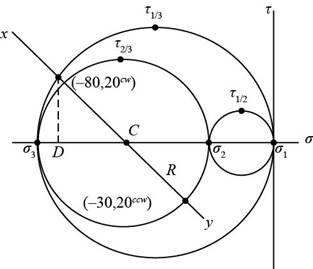
Figure-(1)
(b)
The principal normal stresses.
The principal shear stresses.
The Mohr circle diagram.
If
Answer to Problem 18P
The principal normal stresses are
The principal shear stresses are
The Mohr circle diagram is shown in Figure-(2).
Explanation of Solution
Conclusion:
Substitute
Solve Equation (IX) to obtain roots of Equation as
Substitute
Substitute
Substitute
Thus, the principal shear stresses are
Substitute
Substitute
Substitute
The procedure to draw the Mohr’s circle is given below.
- Draw
- Mark
- Draw three circles with shear stresses as radius.
The figure below shows the Mohr’s Circle.
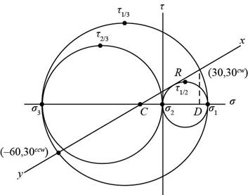
Figure-(2)
(c)
The principal normal stresses.
The principal shear stresses.
The Mohr circle diagram.
If
Answer to Problem 18P
The principal normal stresses are
The principal shear stresses are
The Mohr circle diagram is shown in Figure-(3).
Explanation of Solution
Conclusion:
Substitute
Solve Equation (X) to obtain roots of Equation as
Substitute
Substitute
Substitute
Thus, the principal shear stresses are
Substitute
Substitute
Substitute
The procedure to draw the Mohr’s circle is given below.
- Draw
- Mark
- Draw three circles with shear stresses as radius.
The figure below shows the Mohr’s Circle.
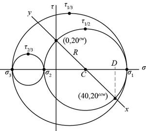
Figure-(3)
(d)
The principal normal stresses.
The principal shear stresses.
The Mohr circle diagram.
If
Answer to Problem 18P
The principal normal stresses are
The principal shear stresses are
The Mohr circle diagram is shown in Figure-(4).
Explanation of Solution
Conclusion:
Substitute
Solve Equation (XI) to obtain roots of Equation as
Substitute
Substitute
Substitute
Thus, the principal shear stresses are
Substitute
Substitute
Substitute
The procedure to draw the Mohr’s circle is given below.
- Draw
- Mark
- Draw three circles with shear stresses as radius.
The figure below shows the Mohr’s Circle.
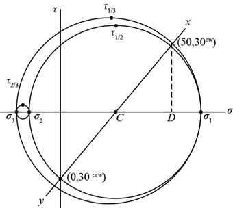
Figure-(4)
Want to see more full solutions like this?
Chapter 3 Solutions
Shigley's Mechanical Engineering Design (McGraw-Hill Series in Mechanical Engineering)


- -26 A rectangular plate of dimensions 125 mm × 75 mm is subjected to tensile stress sy= 67 kPa and compressive stress a. If it is known that the normal stress along the diagonal t—t is ??t= -6.57 kPa, find stress ??y on element A. aarrow_forward-27 A square plate with side dimension of 2 in. is subjected to compressive stress a and tensile stress The stresses on element A oriented at angle ?? x1=45° aresy1= 75 psi. tx1y1= 275 psi. . Find the state of stress on the element lilt is rotated clockwise to align the x3 axis with the horizontal x axis.arrow_forwardAt a point on the surface of an elliptical exercise machine, the material is in biaxial stress with t = 1400 psi and trv = —900 psi, as shown in the figure part a. The figure part b shows an inclined plane aa cut through the same point in the material but oriented at an angle ft Determine the value of the angle 6 between zero and 90° such that no normal stress acts on plane aa. Sketch a stress clement having plane aa as one of its sides and show all stresses acting on the clementarrow_forward
- .4 The stresses on an clement arc known to be sx= 120 MPa, sy= 100 MPa, and txy= 75 MPa. Find the stresses on an inclined section through the element at an angle ? = 45°.arrow_forwardAn element in plane stress on the fuselage of an airplane (figure part a) is subjected to compressive stresses with a magnitude of 42 MPa in the horizontal direction and tensile stresses with a magnitude of 9.5 MPa in the vertical direction (sec figure part b). Also, shear stresses with a magnitude of 15.5 MPa act in the directions shown. Determine the stresses acting on an element oriented at a clockwise angle of 40g from the horizontal. Show these stresses on a sketch of an element oriented at this angle.arrow_forward-18 through 7.4-25 An clement in plane stress is subjected to stresses a,, ay., and axy. (see figure). Using Mohr’s circle, determine (a) the principal stresses and (b) the maximum shear stresses and associated normal stresses. Show all results on sketches of properly oriented elements.arrow_forward
- .4-2 An element in uniaxial stress is subjected to tensile stresses sx= 57 MPa. as shown in the figure. Using Mohr’s circle, determine the following. (a) The stresses acting on an clement oriented at an angle 0 = 33° from the x axis (minus means clockwise). (b) The maximum shear stresses and associated normal stresses. Show all results on sketches of properly oriented elements.arrow_forwardSolve the preceding problem if the norm al and shear stresses acting on the element are sx = 2100 kPa, sy= 300 kPa, and txy= -560 kPa, and the seam is oriented at an angle of 22.5° to the clement.arrow_forwardA prismatic bar with a length L = 3 ft and cross-sectional area A = 8 in2 is compressed by an axial centroidal load P = 10 kips. Determine the complete state of stress acting on an inclined section pq that is cut through the bar at an angle W = 35", and show the stresses on a properly oriented stress element.arrow_forward
- -18 through 7.3-22 An element in plane stress (see figure) is subjected to stresses o, a., and (a) Determine the principal stresses and show them on a sketch of a properly oriented element. (b) Determine the maximum shear stresses and associated normal stresses and show them on a sketch of a properly oriented element. 7.3-18 a=2I50kPa, ay=375kPa.Txy.=-460kPaarrow_forwardThe normal strain in the 45n direction on the surface of a circular tube (sec figure) is 880 × 10 when the torque T = 750 lb-in. The tube is made of copper alloy with G = 6.2 × 10⁶ psi and y = 0.35. If the outside diameter d2of the tube is 0.8 in., what is the inside diameter dt? If the allowable normal stress in the tube is 14 ksi, what is the maximum permissible inside diameter d?arrow_forwardThe stresses acting on a stress element on the arm of a power excavator (see figure) are ax= 52 MPa and txy= 33 MPa (sec figure). What is the allowable range of values for the stress if the maximum shear stress is limited to = 37 MPa?arrow_forward
 Mechanics of Materials (MindTap Course List)Mechanical EngineeringISBN:9781337093347Author:Barry J. Goodno, James M. GerePublisher:Cengage Learning