
Concept explainers
Videos
3–1* to 3–4 Sketch a free-body diagram of each element in the figure. Compute the magnitude and direction of each force using an algebraic or
The free body diagram of each element of the given figure.
The magnitude and direction of each force.
Answer to Problem 1P
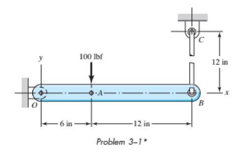
The free body diagram of element OB is shown in Figure (1).
The free body diagram of element BC is shown in Figure (2).
The free body diagram of pin joint C is shown in Figure (3).
The free body diagram of pin joint O is shown in Figure (4).
The magnitude of force at O is
The magnitude of force at B is
The magnitude of force at C is
Explanation of Solution
Figure (1) shows the free body diagram of the element OB.
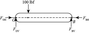
Figure (1)
Write the net moment at point O on the link OB.
Here, perpendicular distance between point O and
Write the net reaction force in the vertical direction on the link OB.
Here, force acting at point O is
Write the net reaction force in the horizontal direction on the link OB.
Here, force acting at point O is
Figure (2) shows the free body diagram of element BC.
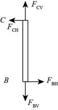
Figure (2)
Write the net reaction force in the horizontal direction on the link BC.
Here, force acting at point B is
Write the net reaction force in the vertical direction on the link OB.
Here, force acting at point C is
Figure (3) shows the free body diagram of pin joint C.
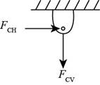
Figure (3)
Write the expression of net reaction force at pin joint C in horizontal direction.
Here, force acting at point C in the horizontal direction is
The force acting in the vertical direction at point C is balanced by the reaction force by link BC at point C.
Figure (4) shows the free body diagram of the pivot point O.
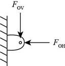
Figure (4)
Write the expression of net reaction force at pin joint O in horizontal direction.
Here, force acting at point O in the horizontal direction is
The force acting in the vertical direction at point O is balanced by the reaction force by link OB at point O.
Conclusion
Substitute
Thus, the vertical component of the force at point
Substitute
Thus, the vertical component of the force at point
Substitute
Thus, the vertical component of the force at point
Substitute
Thus, the horizontal component of the force at point
Substitute
Thus, the horizontal component of the force at point
Thus, the magnitude of force at O is
Thus, the magnitude of force at B is
Thus, the magnitude of force at C is
Want to see more full solutions like this?
Chapter 3 Solutions
SHIGLEY'S MECH.ENGINEERING DESIGN-EBK>I
Additional Engineering Textbook Solutions
Fox and McDonald's Introduction to Fluid Mechanics
Heating Ventilating and Air Conditioning: Analysis and Design
Thermodynamics: An Engineering Approach
Mechanics of Materials (10th Edition)
Mechanics of Materials
Thinking Like an Engineer: An Active Learning Approach (3rd Edition)


- The stresses acting on a stress element on the arm of a power excavator (see figure) are ax= 52 MPa and txy= 33 MPa (sec figure). What is the allowable range of values for the stress if the maximum shear stress is limited to = 37 MPa?arrow_forwardRepeat Problem 11.3-9. Use two C 150 × 12.2 steel shapes and assume that E = 205 GPa and L = 6 m.arrow_forwardSolve the preceding problem for a plate of dimensions 100 mm × 250 mm subjected to a compressive stress of 2.5 MPa in the long direction and a tensile stress of 12.0 MPa in the short direction (see figure).arrow_forward
- A steel punch consists of two shafts: upper shaft and lower shaft. Assume that the upper shaft has a diameter d1= 24 mm and the bottom shaft has a diameter d2= 16 mm. The punch is used to insert a hole in a 4 mm plate, as shown in the figure. If a force P - 70 kN is required to create the hole, what is the average shear stress in the plate and the average compressive stress in the upper and lower shaft of the punch?arrow_forwardA high-strength steel drill rod used for boring a hole in the earth has a diameter of 0.5 in. (see figure). The allowable shear stress in the steel is 40 ksi and the shear modulus of elasticity is 11,600 ksi. What is the minimum required length of the rod so that one end of the rod can be twisted 30º with respect to the other end without exceeding the allowable stress? If the shear strain in part (a) is limited to 3.2 × 10⁻³ , what is the minimum required length of the drill rod?arrow_forwardSolve the preceding problem if the diameter is 480 mm, the pressure is 20 MPa, the yield stress in tension is 975 MPa, the yield stress in shear is 460 MPa, the factor of safety is 2,75, the modulus of elasticity is 210 GPa, Poissorfs ratio is 0.28, and the normal strain must not exceed 1190 x 10" . For part (b), assume that the tank thickness is 8 mm and the measured normal strain is 990 x 10~ .arrow_forward
- A mountain bike is moving along a flat path at constant velocity. At some instant, the rider (weight = 670 N) applies pedal and hand forces, as shown in the figure part a. (a) Find reaction forces at the front and rear hubs. (Assume that the bike is pin supported at the rear hub and roller supported at the front hub.) (b) Find internal stress resultants N, V, and M in the inclined seat post (see figure part barrow_forwardA circular tube of aluminum is subjected to torsion by torques T applied at the ends (see figure). The bar is 24 in. long, and the inside and outside diameters are 1.25 in. and 1.75 in., respectively. It is determined by measurement that the angle of twist is 4° when the torque is 6200 lb-in. Calculate the maximum shear stress in the tube, the shear modulus of elasticity G, and the maximum shear strain (in radians). If the maximum shear strain in the tube is limited to 2.5 × 10⁻³ and the inside diameter is increased to 1.375 in., what is the maximum permissible torque?arrow_forwardCompare the angle of twist 1 for a thin-walled circular tube (see figure) calculated from the approximate theory for thin-walled bars with the angle of twist 2 calculated from the exact theory of torsion for circular bars, Express the ratio 12terms of the non-dimensional ratio ß = r/t. Calculate the ratio of angles of twist for ß = 5, 10, and 20. What conclusion about the accuracy of the approximate theory do you draw from these results?arrow_forward
- A steel cable with a nominal diameter of 25 mm (see Table 2-1) is used in a construction yard to lift a bridge section weighing 38 kN. as shown in the figure. The cable has an effective modulus of elasticity E = 140 GPa. (a) If the cable is 14 m long, how much will it stretch when the load is picked up? (b) If the cable is rated for a maximum load of 70 kN, that is the factor of safety with respect to failure of the cable?arrow_forwardA punch for making a slotted hole in ID cards is shown in the figure part a. Assume that the hole produced by the punch can be described as a rectangle (12 mm X 3 mm) with two half circles (r = 1.5 mm) on the left and the right sides. If P = 10 N and the thickness of the ID card is 1 mm, what is the average shear stress in the card?arrow_forwardA capped cast-iron pipe is compressed by a brass rod, as shown. The mil is turned until it is just snug, then add an additional quarter turn to pre-compress the cast-iron pipe. The pitch of the threads of the bolt ap = 52 mils (a mil is one-thousandth of an inch). Use the numerical properties provided. (a) What stresses a and arwill be produced in the cast-iron pipe and brass rod. respectively, by the additional quarter turn of the nut? (b) Find the bearing stress ahbeneath the washer and the shear stress t(in the steel cap.arrow_forward
 Mechanics of Materials (MindTap Course List)Mechanical EngineeringISBN:9781337093347Author:Barry J. Goodno, James M. GerePublisher:Cengage Learning