
Concept explainers
Videos
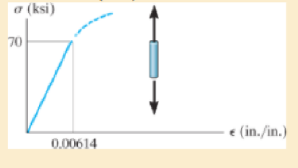
The elastic portion of the tension stress-strain diagram for an aluminum alloy is shown in the figure. The specimen used for the test has a gage length of 2 in. and a diameter of 0.5 in. When the applied load is 9 kip, the new diameter of the specimen is 0.49935 in. Calculate the shear modulus Gal for the aluminum.
The shear modulus for an aluminum alloy
Answer to Problem 3.1RP
The shear modulus for an aluminum alloy is
Explanation of Solution
Given information:
Gage length is
The diameter of the specimen is
The axial load acts on the specimen is
The new diameter of the specimen is
Calculation:
Calculate the modulus of elasticity for aluminum
Here, the stress is
Refer the stress-strain diagram.
The value of stress is 70 ksi and the value of strain is
Substitute 70 ksi for
The expression to find the cross-sectional area of the specimen
Here, the diameter of the specimen is
Substitute
Find the value of stress when the specimen is loaded with a 9 kip load using the relation:
Here, the load is P.
Substitute 9 kip for P and
The expression to find the strain in the longitudinal or axial direction
Here, the Young’s modulus of the aluminum is
Substitute
Find the strain in lateral direction
Here, the new diameter is
Substitute
Find the Poisson’s ratio
Substitute
Calculate the modulus of rigidity for the specimen
Substitute
Therefore, the shear modulus for an aluminum alloy is
Want to see more full solutions like this?
Chapter 3 Solutions
Mechanics of Materials Plus Mastering Engineering with Pearson eText - Access Card Package (10th Edition)
Additional Engineering Textbook Solutions
Automotive Technology: Principles, Diagnosis, and Service (5th Edition)
Engineering Mechanics: Statics
Applied Statics and Strength of Materials (6th Edition)
INTERNATIONAL EDITION---Engineering Mechanics: Statics, 14th edition (SI unit)
Statics and Mechanics of Materials (5th Edition)
Engineering Mechanics: Statics & Dynamics (14th Edition)


- A spherical balloon with an outer diameter of 500 mm and thickness 0.3 mm is filled with a gas. Calculate maximum permissible pressure in the balloon if the allowable normal strain at the outer surface of the balloon is O.h Assume E = 4 MPa and v = 0,45.arrow_forwardA wine of length L = 4 ft and diameter d = 0.125 in. is stretched by tensile forces P = 600 lb. The wire is made of a copper alloy having a stress-strain relationship that may be described mathematically by =18,0001+30000.03(=ksi) in which is nondimensional and has units of kips per square inch (ksi). (a) Construct a stress-strain diagram for the material. (bj Determine the elongation, of the wire due to the Forces P. (c) IF the forces are removed, what is the permanent set of the bar? (d) If the forces are applied again, what is the proportional limit?arrow_forwardA spherical balloon is filled with a gas. The outer diameter of the balloon is 20 in. and the thickness is 0,012 in. Calculate the maximum permissible pressure in the balloon if the allowable tensile stress and the allowable shear stress in the balloon are 1 ksi and 0.3 ksi, respectively.arrow_forward
- An aluminum bar subjected to tensile Forces P has a length L = 150 in. and cross-sectional area A = 2.0 in2 The stress-strain behavior of the aluminum may be represented approximately by the bilinear stress-strain diagram shown in the figure. Calculate the elongation S of the bar for each of the following axial loads: p = 8 kips, 16 kips. 24 kips, 32 kips, and 40 kips. From these results, plot a diagram of load P versus elongation S (load-displacement diagram).arrow_forwardA prismatic bar in tension has a length L = 2.0 m and cross-sectional area A =249 mn2. The material of the bar has the stress-strain curve shown in the figure. Determi ne t he elongation 5 of the bar for each of the following axial loads: P = 10 kN, 20 kN, 30 kN, 40 kN. and 45 kN. From these results, plot a diagram of load P versus elongation 5 (load-displacement diagram).arrow_forwardA joint between two glass plates A and B is filled with a flexible epoxy that bonds securely to the glass. The height of the joint is/p = 0.5 in, its length is L = 30 in, and its thickness is/ = 0.5 in. Shear force of I' = 25 kips is applied to the joint. Calculate the displacement of the joint if the shear modulus of elasticity G of the epoxy is 100 ksi. Calculate the average shear strain in the epoxy.arrow_forward
- Solve the preceding problem if the cross- sectional dimensions are b = 1.5 in. and h = 5.0 in., the gage angle is ß = 750, the measured strains are = 209 × 10-6 and B = -110 × 10, and the material is a magnesium alloy with modulus E = 6.0 X 10⁶ psi and Poisson’s ratio v = 0.35.arrow_forwardA steel bar has a square cross section of width b = 2.0 in. (sec figure). The bar has pinned supports at the ends and is 3.0 ft long. The axial forces acting at the end of the bar have a resultant P = 20 kips located at distance e = 0,75 in, from the center of the cross section. Also, the modulus of elasticity of the steel is 29,000 ksi. Determine the maximum compressive stress max, in the bar. If the allowable stress in the steel is 18,000 psi, what is the maximum permissible length Lmaxof the bar?arrow_forwardA rubber ball (sec figure) is inflated to a pressure of 65 kPa. At that pressure, the diameter of the ball is 240 mm and the wall thickness is 1.25 mm. The rubber has a modulus of elasticity E = 3,7 MPa and Poisson's ratio v = 0.48. (a) Determine the maximum stress and strain in the ball, (b) If the strain must be limited to 0.425, Find the minimum required wall thickness of the ball.arrow_forward
- A circular aluminum tube of length L = 600 mm is loaded in compression by forces P (see figure). The outside and inside diameters are d2= 75 mm and d1= 63 mm, respectively. A strain gage is placed on the outside of the lube to measure normal strains in the longitudinal direction. Assume that E = 73 GPa and Poissons ratio is v = 0.33. (a) IF the compressive stress in the tube is 57 MPa, what is the load P? (b) If the measured strain is e = 78 J X 10-6, what is the shorteningarrow_forwardAn clement of material in plane strain (see figure) is subjected to strains ex= 480 × 10-6, Ey= 70 × l0-6, and yxy= 420 × l0-6. Determine the following quantities: (a) the strains for an element oriented at an angle 0 = 75°, (b) the principal strains, and (c) the maximum shear strains. Show the results on sketches of properly oriented elements.arrow_forwardA circular cylindrical steel tank (see figure) contains a volatile fuel under pressure, A strain gage at point A records the longitudinal strain in the tank and transmits this information to a control room. The ultimate shear stress in the wall of the tank is 98 MPa, and a factor of safety of 2,8 is required. (a) At what value of the strain should the operators take action to reduce the pressure in the tank? (Data for the steel are modulus of elasticity E = 210 GPa and Poisson's ratio v = 0.30.) (b) What is the associated strain in the radial directionarrow_forward
 Mechanics of Materials (MindTap Course List)Mechanical EngineeringISBN:9781337093347Author:Barry J. Goodno, James M. GerePublisher:Cengage Learning