
Videos
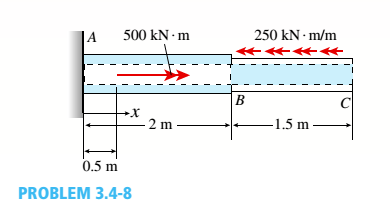
Two sections of steel drill pipe, joined by bolted flange plates at Ä are being tested to assess the adequacy of both the pipes. In the test, the pipe structure is fixed at A, a concentrated torque of 500 kN - m is applied at x = 0.5 m, and uniformly distributed torque intensity t1= 250 kN m/m is applied on pipe BC. Both pipes have the same inner diameter = 200 mm. Pipe AB has thickness tAB=15 mm, while pipe BC has thickness TBC= 12 mm. Find the maximum shear stress and maximum twist of the pipe and their locations along the pipe. Assume G = 75 GPa.
The maximum shear stress.
The maximum angle of twist.
Answer to Problem 3.4.8P
The maximum shear stress is
The maximum angle of twist is
Explanation of Solution
Given information:
The concentrated torque is
Write the expression for torque at B.
Here, torque at B is
Write the expression for torque at AD.
Here, torque at AD is
Write the expression for polar moment of inertia of section BC .
Here, polar moment of inertia is
Write the expression for polar moment of inertia of section AB .
Here, polar moment of inertia is
Write the expression for maximum shear stress for section BC .
Here, maximum shear stress for section BC is
Write the expression for maximum shear stress for section BC .
Here, maximum shear stress for section BC is
Write the expression for angle of twist.
Here, function for angle of twist is
Write the expression for angle of twist.
Write the expression for angle of twist.
Here, dummy variable is
Calculation:
Substitute
Substitute
Substitute
Substitute
Substitute
The maximum shear stress in section AB is
Substitute
The maximum shear stress in section BC is
Substitute
Substitute
Substitute
Substitute
Substitute
Substitute
The maximum angle of twist occurs at C .
Convert twist angle in degrees.
Conclusion:
The maximum shear stress is
The maximum angle of twist is
Want to see more full solutions like this?
Chapter 3 Solutions
Mechanics of Materials (MindTap Course List)


- , Solve the preceding problem using the numerical data: /) = 90mm, h = 280 mm, d = 210 mm, q = 14 kN/m, and L = L2 m.arrow_forward.17 A mountain-bike rider going uphill applies torque T = Fd(F = l5lb, d = 4 in.) to the end of the handlebars ABCD by pulling on the handlebar extenders DE. Consider the right half of the handlebar assembly only (assume the bars are fixed at the fork at A). Segments AB and CD are prismatic with lengths L, = 2 in.andL3 = 8.5 in, and with outer diameters and thicknesses d01 = 1.25 in. 101 = 0.125 in. and d03 = O.87in.,i03 = 0.ll5in, respectively as shown. Segment BC’ of length L, = 1.2 in. however. is tapered, and outer diameter and thickness vary linearly between dimensions at B and C. Consider torsion effects only. Assume G = 4000 ksi is constant. Derive an integral expression for the angle of twist of half of the handlebar tube when it is subjected to torque T = Fd acting at the end. Evaluate ‘b1-, for the given numerical1ues.arrow_forwardA vertical pole consisting of a circular tube of outer diameter 5 in. and inner diameter 4.5 in. is loaded by a linearly varying distributed force with maximum intensity of q0, Find the maximum shear stress in the pole.arrow_forward
- A propeller shaft for a small yacht is made of a solid steel bar 104 mm in diameter. The allowable stress in shear is 48 MPa, and the allowable rate of twist is 2.0° in 3.5 meters. (a) Assuming that the shear modulus of elasticity is G = 80 GPa, determine the maximum torque that can be applied to the shaft. (b) Repeat part (a) if the shaft is now hollow with an inner diameter of 5d18. Compare values to corresponding values from part (a).arrow_forwardSolve the preceding problem if the thickness of the steel plate is. t = 12 mm. the gage readings are x = 530 × 10-6 (elongation) and y = -210 -× l0-6 (shortening), the modulus is E = 200 GPa, and Poisson’s ratio is v = 0.30.arrow_forwardA hollow tube ABCDE constructed of monel metal is subjected to five torques acting in the directions shown in the figure. The magnitudes of the torques are T1= 1000 lb-in., T2= T4= 500 lb-in., and T3= T5= 800 lb-in. The tube has an outside diameter of d2= 1.0 in. The allowable shear stress is 12,000 psi and the allowable rate of twist is 2.0°/ft. Determine the maximum permissible inside diameter d1, of the tube.arrow_forward
- A thin-walled aluminum tube of rectangular cross section (sec fig me) has a centerline dimensions b = 6.0 in. and b = 4.0 in. The wall thickness t is constant and equal to 0.25 in. Determine the shear stress in the tube due to a torque T = 15 kip-in. Determine the angle of twist (in degrees) if the length L of the tube is 50 in. and the shear modulus G is 4.0 x 10⁶ psi.arrow_forwardSolve the preceding problem if the cross- sectional dimensions are b = 1.5 in. and h = 5.0 in., the gage angle is ß = 750, the measured strains are = 209 × 10-6 and B = -110 × 10, and the material is a magnesium alloy with modulus E = 6.0 X 10⁶ psi and Poisson’s ratio v = 0.35.arrow_forwardA circular steel tube with an outer diameter of 75 mm and inner diameter of 65 mm is subjected to torques 7"at its ends. Calculate the maximum permissible torque 7jliajl if the allowable normal strain is ea= 5 X 10"4 Assume that G = 15 GPa.arrow_forward
- A motor driving a solid circular steel shaft with diameter d = 1.5 in, transmits 50 hp to a gear at B, The allowable shear stress in the steel is 6000 psi. Calculate the required speed of rotation (number of revolutions per minute) so that the shear stress in the shaft does not exceed the allowable limit.arrow_forwardA tapered bar AB with a solid circular cross section is twisted by torques T = 36,000 lb-in. (sec figure). The diameter of the bar varies linearly from dAat the left-hand end to dBat the right-hand end. The bar has length L = 4,0 ft and is made of an aluminum alloy having shear modulus of elasticity G = 3.9 × 10⁶ psi. The allowable shear stress in the bar is 15,000 psi and the allowable angle of twist is 3.0°. If the diameter at end B is 1.5 times the diameter at end A, what is the minimum required diameter dAat end A?arrow_forwardSolve the preceding problem for a W 200 × 41,7 shape with h = 166 mm, h = 205 mm. rw = 7.24 mm, tE= ILS mm,andV = 38 kN.arrow_forward
 Mechanics of Materials (MindTap Course List)Mechanical EngineeringISBN:9781337093347Author:Barry J. Goodno, James M. GerePublisher:Cengage Learning