
Concept explainers
Videos
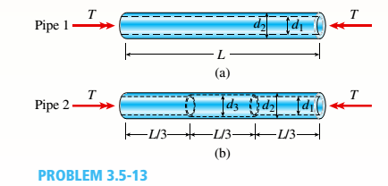
Two circular aluminum pipes of equal length L = 24 in. arc loaded by torsional moments T (sec figure). Pipe I has outside and inside diameters d2= 3 in. and L2, = 2.5 in., respectively. Pipe 2 has a constant outer diameter of d2along its entire length L and an inner diameter of d1but has an increased inner diameter of d3= 2.65 in. over the middle third.
Assume that E = 10,400 ksi, u = 0.33, and allowable shear stress ra= 6500 psi.
- Find the maximum acceptable torques that can be applied to Pipe 1; repeat for Pipe 2.
(a)
The maximum acceptable torques for pipe (1).
The maximum acceptable torques for pipe (2).
Answer to Problem 3.5.13P
Maximum acceptable torques for pipe (1) is =
Maximum acceptable torques for pipe (2) is =
Explanation of Solution
Given information:
The following figure shows the free body diagram of pipe 1:
Figure-(1) shows the diagram of two pipes:
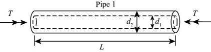
Figure-(1)
The following figure shows the free body diagram of pipe 2:
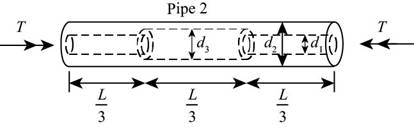
Figure-(2)
The length of pipe is
Write the expression for polar moment of inertia for pipe (1)
Here, the polar moment of inertia is
Write the expression for maximum torque for pipe (1)
Here, acceptable shear stress is
Write the expression for polar moment of inertia for pipe (2)
Here, the polar moment of inertia is
Write the expression for maximum torque for pipe (2)
Here, acceptable shear stress is
Calculation:
Substitute,
Substitute
Substitute,
Substitute
Conclusion:
Maximum acceptable torques for pipe (1) is =
Maximum acceptable torques for pipe (2) is =
(b)
The maximum acceptable length of the middle segment.
Answer to Problem 3.5.13P
The maximum acceptable length of the middle segment.
Explanation of Solution
Given information:
Maximum twist of pipe (2) cannot exceed
Write the expression for the angle of twist for pipe (1).
Here the angle of twist is
Write the expression for total angle of twist for pipe (2)
Here, the total angle of twist is
Write the expression for the length of the segment
Write expression for the angle of twist in the section
Write expression for the angle of twist in the section
Write expression for the angle of twist in the section
Substitute
Write the expression for relation between
Calculation:
Substitute
Substitute
Substitute
Conclusion:
The maximum acceptable length of the middle segment is =
(c)
The inner diameter for the given parameters.
Answer to Problem 3.5.13P
The inner diameter for the given parameters is =
Explanation of Solution
Given information:
the maximum torque carried by pipe (2) is
Write the expression for allowable torque.
Here, the allowable torque is
Substitute
Calculation:
Substitute
Conclusion:
The inner diameter for the given parameters is
(c)
Applied torque on pipe (1)
Maximum twist of pipe (1)
Answer to Problem 3.5.13P
Applied torque on pipe (1) is =
Applied torque on pipe (2) is =
Maximum twist of pipe (1) is =
Explanation of Solution
Write the expression for maximum shear strain.
Here, maximum shear strain is
Write the expression for maximum shear stress.
Here, the maximum shear stress is
Write the expression for shear modulus of elasticity.
Write the expression for maximum torque for pipe (1)
Write the expression for maximum angle of twist for pipe (1)
Maximum angle of twist in pipe (1) is
Calculation:
Substitute
Substitute
Substitute
Substitute
Substitute
Substitute
Conclusion:
Applied torque on pipe (1) is =
Applied torque on pipe (2) is =
Maximum twist of pipe (1) is =
Want to see more full solutions like this?
Chapter 3 Solutions
Mechanics of Materials (MindTap Course List)


- A cantilever beam(Z, = 6 ft) with a rectangular cross section (/> = 3.5 in., h = 12 in.) supports an upward load P = 35 kips at its free end. (a) Find the state of stress ((7T, o^., and r in ksi) on a plane-stress element at L/2 that is i/ = 8 in. up from the bottom of the beam. Find the principal normal stresses and maximum shear stress. Show these stresses on sketches of properly oriented elements. (b) Repeat part (a) if an axial compressive centroidal load N = 40 kips is added at Barrow_forwardA square steel tube of a length L = 20 ft and width b2= 10.0 in. is hoisted by a crane (see figure). The lube hangs from a pin of diameter d that is held by the cables at points A and B. The cross section is a hollow square with an inner dimension b1= 8.5 in. and outer dimension b2= 10,0 in. The allowable shear stress in the pin is 8,700 psi. and the allowable bearing stress between the pin and the tube is 13,000 psi. Determine the minimum diameter of the pin in order to support the weight of the tube. Note: Disregard the rounded corners of the tube when calculating its weight.arrow_forwardA rigid Trame ABC is formed by welding two steel pipes at B (see figure). Each pipe has cross-sectional area A = 11.31 × 10 mm2, moment of inertia I = 46.37 × 106 mm4, and outside diameter d = 200 mm. Find the maximum tensile and compressive stresses e1and e2, respectively, in the frame due to the load P = 8.0 kN if L = H = 1.4 m.arrow_forward
- A steel bracket of solid circular cross section is subjected to two loads, each of which is P = 4.5 kN at D (see figure). Let the dimension variable be b = 240 mm. Find the minimum permissible diameter dmaxof the bracket if the allowable normal stress is 110 M Pa. Repeat part (a), including the weight of the bracket. The weight density of steel is 77.0 kN/m3.arrow_forwardA simple beam of span length 3.2 m carries a uniform load of intensity 48 kN/m, The cross section of the beam is a hollow box with wood flanges and steel side plates, as shown in the figure. The wood flanges are 75 mm x 100 mm in cross section, and the steel plates are 300 mm deep. What is the required thickness t of the steel plates if the allowable stresses are 120 M Pa for the steel and 6,5 M Pa for the wood? (Assume that the moduli of elasticity for the steel and wood are 210 GPa and 10 GPa, respectively, and disregard the weight of the beam.)arrow_forwardA cylindrical pressure vessel having a radius r = 14 in. and wall thickness t = 0,5 in, is subjected to internal pressure p = 375 psi, In addition, a torque T = 90 kip-ft acts at each end of the cylinder (see figure), (a) Determine the maximum tensile stress ctniXand the maximum in-plane shear stress Tmjv in the wall of the cylinder. (b) If the allowable in-plane shear stress is 4.5 ksi, what is the maximum allowable torque T\ (c) If 7 = 150 kip-ft and allowable in-plane shear and allowable normal stresses are 4.5 ksi and 11.5 ksi, respectively, what is the minimum required wall thicknessarrow_forward
- A round bar ABC of length 2L (see figure) rotates about an axis through the midpoint C with constant angular speed w (radians per second). The material of the bar has weight density y. (a) Derive a formula for the tensile stress a’ in the bar as a function of the distance x from the midpoint C. (b) What is the maximum tensile stress a max?arrow_forwardA vertical pole of solid, circular cross section is twisted by horizontal forces P = 1100 lb acting at the ends of a rigid horizontal arm AB (see figure part a). The distance from the outside of the pole to the line of action of each force is c = 5.0 in. (see figure part b) and the pole height is L = 14in. (a) If the allowable shear stress in the pole is 4500 psi, what is the minimum required diameter dminof the pole? Find the torsional stiffness of the pole (kip-in./rad). Assume that G = 10,800 ksi. If two translational springs, each with stiffness k = 33 kips/in., are added at 2(75 from A and B (see figure part c), repeat part (a) to find dmin. Hint: Consider the pole and pair of springs as "springs in parallel."arrow_forwardA hollow circular tube having an inside diameter of 10.0 in, and a wall thickness of 1.0 in. (see figure) is subjected to a torque T = 1200 kip-in. Determine the maximum shear stress in the tube using (a) the approximate theory of thin-walled tubes, and (b) the exact torsion theory. Does the approximate theory give conservate or nonconservative results?arrow_forward
- Beam ABC with an overhang BC is subjected to a linearly varying distributed load on span AB with peak: intensity q0= 2500 N/m and a point load P = 1250 N applied at C. The beam has a width ft = 100 mm and depth h = 200 mm. Find the state of plane stress at point D located 150 mm below the top of the beam and 0.2 m to the left of point B. Also find the principal stresses at D>Neglect the weight of the beam.arrow_forwardA thin-walled steel tube of rectangular cross section (see figure) has centerline dimensions b = 150 mm and h = 100 mm. The wall thickness t is constant and equal to 6.0 mm. Determine the shear stress in the tube due to a torque T = 1650 N · m. Determine the angle of twist (in degrees) if the length L of the tube is 1.2 m and the shear modulus G is 75 GPa.arrow_forward-21 Plastic bar AB of rectangular cross section (6 = 0.75 in. and h = 1.5 in.) and length L = 2 Ft is Fixed at A and has a spring support (Ar = 18 kips/in.) at C (see figure). Initially, the bar and spring have no stress. When the temperature of the bar is raised hy foot. the compressive stress on an inclined plane pq at Lq = 1.5 Ft becomes 950 psi. Assume the spring is massless and is unaffected by the temperature change. Let a = 55 × l0-6p and E = 400 ksi. (a) What is the shear stresst9 on plane pq? What is angle 07 =1 Draw a stress element oriented to plane pq, and show the stresses acting on all laces of this element. (c) If the allowable normal stress is ± 1000 psi and the allowable shear stress is ±560 psi, what is the maximum permissible value of spring constant k if the allowable stress values in the bar are not to be exceeded? (d) What is the maximum permissible length L of the bar if the allowable stress values in the bar are not be exceeded? (Assume £ = IB kips/in.) (e) What is the maximum permissible temperature increase (A7") in the bar if the allowable stress values in the bar are not to be exceeded? (Assume L = 2 ft and k = L& kips/inarrow_forward
 Mechanics of Materials (MindTap Course List)Mechanical EngineeringISBN:9781337093347Author:Barry J. Goodno, James M. GerePublisher:Cengage Learning