
Steel Design (Activate Learning with these NEW titles from Engineering!)
6th Edition
ISBN: 9781337094740
Author: Segui, William T.
Publisher: Cengage Learning
expand_more
expand_more
format_list_bulleted
Concept explainers
Videos
Textbook Question
Chapter 3, Problem 3.6.6P
Use load and resistance factor design and select a
Expert Solution & Answer

Trending nowThis is a popular solution!

Students have asked these similar questions
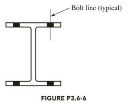
Use load and resistance factor design and select a W shape with a nominal depth of 10 inches (a W10) to resist a dead load of 175 kips and a live load of 175 kips. The connection will be through the flanges with two lines of 1 1/4–inch-diameter bolts in each flange, as shown. Each line contains more than two bolts. The length of the member is 30 feet. Use A242 steel.
A plate 1⁄2 3 4 of A36 steel is used as a tension member to carry a service dead load of 6 kips and a service live load of 18 kips. It is to be attached to a 3⁄8-inch gusset plate, as shown in Figure. Design a welded connection.
For the clevis connection shown, determine the shear stress in the 20-mm-diameter bolt for an applied load of P = 130 kN.
Chapter 3 Solutions
Steel Design (Activate Learning with these NEW titles from Engineering!)
Ch. 3 - Prob. 3.2.1PCh. 3 - Prob. 3.2.2PCh. 3 - Prob. 3.2.3PCh. 3 - Prob. 3.2.4PCh. 3 - Prob. 3.2.5PCh. 3 - Prob. 3.2.6PCh. 3 - Prob. 3.3.1PCh. 3 - Prob. 3.3.2PCh. 3 - Prob. 3.3.3PCh. 3 - Prob. 3.3.4P
Ch. 3 - Prob. 3.3.5PCh. 3 - Prob. 3.3.6PCh. 3 - Prob. 3.3.7PCh. 3 - Prob. 3.3.8PCh. 3 - Prob. 3.4.1PCh. 3 - Prob. 3.4.2PCh. 3 - Prob. 3.4.3PCh. 3 - Prob. 3.4.4PCh. 3 - Prob. 3.4.5PCh. 3 - Prob. 3.4.6PCh. 3 - Prob. 3.5.1PCh. 3 - Prob. 3.5.2PCh. 3 - Prob. 3.5.3PCh. 3 - Prob. 3.5.4PCh. 3 - Prob. 3.6.1PCh. 3 - Prob. 3.6.2PCh. 3 - Prob. 3.6.3PCh. 3 - Select an American Standard Channel shape for the...Ch. 3 - Prob. 3.6.5PCh. 3 - Use load and resistance factor design and select a...Ch. 3 - Select a threaded rod to resist a service dead...Ch. 3 - Prob. 3.7.2PCh. 3 - Prob. 3.7.3PCh. 3 - Prob. 3.7.4PCh. 3 - Prob. 3.7.5PCh. 3 - Prob. 3.7.6PCh. 3 - Prob. 3.8.1PCh. 3 - Prob. 3.8.2PCh. 3 - Prob. 3.8.3PCh. 3 - Prob. 3.8.4PCh. 3 - Prob. 3.8.5P
Knowledge Booster


Learn more about
Need a deep-dive on the concept behind this application? Look no further. Learn more about this topic, civil-engineering and related others by exploring similar questions and additional content below.Similar questions
- Use an elastic analysis and compute the extra load in the weld (in kips per inch of length) caused by the eccentricity.arrow_forwardSelect an American Standard Channel shape for the following tensile loads: dead load = 54 kips, live load = 80 kips, and wind load = 75 kips. The connection will be with longitudinal welds. Use an estimated shear lag factor of U = 0.85. (In a practical design, once the member was selected and the connection designed, the value of U would be computed and the member design could be revised if necessary.) The length is 17.5 ft. Use Fy=50 ksi and Fu=65 ksi. a. Use LRFD. b. Use ASD.arrow_forwardA bolted connection shown in figure A uses the friction type connection with 22mm diameter A 325 bolt.(a) Compute the force P required to cause a slip of the 22mm diam. bolt if the slipcoefficient is 0.34 when the section is subjected to a pre-tension load of 174kN(b) Using the force P, compute nominal shear stress.(c) Compute the factor of safety against a slip of a 22mm diam. bolt if the allowable nominal shear is 120MPa. NOTE: SHOW DRAWINGS AND SOLUTIONS.arrow_forward
- Select a double-angle tension member and design a welded connection to resist a dead load of 12 kips and a live load of 36 kips. The member will be 16 feet long and will be connected to a 5/8-inch-thick gusset plate. Use A36 steel for both the tension member and the gusset plate. Show your results on a sketch, complete with dimensions.arrow_forwardProb 01: An 18” depth beam is bolted to a 24” depth girder is connected similar to that in figure shown below. Thediameter of the rivet is 20mm and the angles are each 100mm x 100mm x 12mm thick. For each bolt, assume thatthe allowable bearing stress is 220 MPa. Determine the allowable load P in KN on the connection. *show all theload P in kN for bearing stressBeam web thickness = 5mmGirder web thickness =arrow_forwardf. Calculate the maximum safe load "P" in KN Two A36 16mm Thick Steel Plates Are Connected By Four Rivets With Fv=152 MPa As Shown. Given: Rivet Dia 20 mm x=100 mmarrow_forward
- I am ok with parts a) and c) but regarding the part b) I think we should mention the number of loops so the equation should be : SI = ext + int - releases = react. - (3 equ) + (3 equ) ( nb of loops) - releases ( no hinges here )= (4) - (3) + (3)(1) - 0 = 4h degree and if I used the simple method, I brake the frame into 2 membersso r= 2+2+3+3=10 n= 2 membersso r> 3n by 4 degree Does it make sense?arrow_forwardA WT10.5 x 31 is used as a bracket to transmit a 60-kip service load to a W14 x 90 column, as previously shown in Figure . The load consists of 15 kips dead load and 45 kips live load. Four 7⁄8-inch-diameter Group A bolts are used. The column is of A992 steel, and the bracket is A36. Assume all spacing and edge-distance requirements are satisfied, including those necessary for the use of the nominal strength in bearing deformation (i.e., 2.4dtFu)*, and determine the adequacy of the bolts for the following types of connections: (a) bearing-type connection with the threads in shear and (b) slip-critical connection with the threads in shear.arrow_forwardDesign a framed beam connection for a W18 x 50 to support a dead load reaction of 30 k and a live load reaction of 20 k, using the LRFD and ASD methods.The beam’s top flange is to be coped for a 2-in depth, and 7/8-in A325-X bolts in standard-size holes are to be used.The beam is connected to a W27 x 146 girder. Connection is A36,while W shapes are A992arrow_forward
- A 15" x 3/8" bar of A572 Gr. 50 steel is used as a tension member. It is connected to a gusset plate with 7/8-in diameter bolts as shown in the figure. Use s = 2.0 and g = 3.0.a) Determine the design tensile strength of the section based on yielding of the gross area.b) Determine the critical net area of the connection shown.arrow_forwardDetermine the resultant load on the most stressed bolt in the eccentrically loaded connections shown, using the elastic method.arrow_forward4.9-1 Verify the value of ry given in Part 1 of the Manual for the double-angle shape 2L4× 31⁄2 × 1⁄4 SLBB. The angles will be connected to a 3⁄8 -inch-thick gusset plate.arrow_forward
arrow_back_ios
SEE MORE QUESTIONS
arrow_forward_ios
Recommended textbooks for you
 Steel Design (Activate Learning with these NEW ti...Civil EngineeringISBN:9781337094740Author:Segui, William T.Publisher:Cengage Learning
Steel Design (Activate Learning with these NEW ti...
Civil Engineering
ISBN:9781337094740
Author:Segui, William T.
Publisher:Cengage Learning
CE 414 Lecture 02: LRFD Load Combinations (2021.01.22); Author: Gregory Michaelson;https://www.youtube.com/watch?v=6npEyQ-2T5w;License: Standard Youtube License