
(a)
The section for loads given loads using load and resistance factor design (LRFD) method.
Answer to Problem 3.8.1P
The section for loads given loads using load and resistance factor design (LRFD) method is
Explanation of Solution
Given data:
Length of the connection is
Spacing of truss in the roof system is
Snow load is
Weight of roofing is
Section for the purlins is
Weight of the truss is
Calculation:
Calculate the snow load.
Calculate the load due to purlins.
Calculate the weight of the truss.
Calculate the slant height of the roof.
Calculate the weight of the roof.
Write the expression to calculate the total dead load.
Here, total dead load is
Substitute
Calculate the factored load using following load combination.
Here, factored load is
Substitute
Write the expression to calculate the exterior joint load.
Here, load on the exterior joint is
Substitute
Consider the free body diagram of the truss shown below.
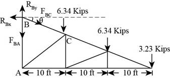
Figure-(1)
Write the expression to calculate the moment about point
Substitute
Solve further.
Consider joint
Write the expression for summation of forces acting in the horizontal direction.
Here, summation of all horizontal forces is
Substitute
Write the expression to calculate the required area.
Here, gross area is
Substitute
Write the expression to calculate the required area.
Here, effective area is
Substitute
Calculate the effective length of the truss.
Calculate the radius of gyration.
Substitute
Use section
Write the expression to calculate reduction factor.
Here, reduction factor is
Substitute
Write the expression to calculate the effective area for the section.
Substitute
Conclusion:
Since the gross area, net area and radius of gyration for this greater than the calculated value,
(b)
The section for loads given loads using allowable strength design (ASD) method.
Answer to Problem 3.8.1P
The section for loads given loads using allowable strength design (ASD) method is
Explanation of Solution
Given data:
Length of the connection is
Spacing of truss in the roof system is
Snow load is
Weight of roofing is
Section for the purlins is
Weight of the truss is
Calculation:
Calculate the ultimate load using the following load combination.
Here, ultimate load is
Substitute
Write the expression to calculate the exterior joint load.
Here, load on the exterior joint is
Substitute
Consider the free body of the truss as shown below.
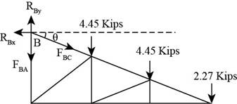
Figure-(2)
Write the expression to calculate the moment about point
Substitute
Solve further.
Consider joint
Write the expression for summation of forces acting in the horizontal direction.
Here, summation of all horizontal forces is
Substitute
Write the expression to calculate the required area.
Here, gross area is
Substitute
Write the expression to calculate the required area.
Here, effective area is
Substitute
Calculate the effective length of the truss.
Calculate the radius of gyration.
Substitute
Use section
Write the expression to calculate reduction factor.
Here, reduction factor is
Substitute
Write the expression to calculate the effective area for the section.
Substitute
Conclusion:
Since the gross area, net area and radius of gyration for this greater than the calculated value,
Want to see more full solutions like this?
Chapter 3 Solutions
Steel Design (Activate Learning with these NEW titles from Engineering!)

- Use load and resistance factor design and select a W shape with a nominal depth of 10 inches (a W 10) to resist a dead load of 175 kips and a live load of 175 kips. The connection will be through the flanges with two lines of 11 4 -inch-diameter bolts in each flange, as shown in Figure P3.6-6. Each line contains more than two bolts. The length of the member is 30 feet. Use A588 steal.arrow_forwardA 15" x 3/8" bar of A572 Gr. 50 steel is used as a tension member. It is connected to a gusset plate with 7/8-in diameter bolts as shown in the figure. Use s = 2.0 and g = 3.0. Determine the critical net area of the connection shown. Determine the design tensile strength of the section based on yielding of the gross area.arrow_forwardA 15" x 3/8" bar of A572 Gr. 50 steel is used as a tension member. It is connected to a gusset plate with 7/8-in diameter bolts as shown in the figure. Use s = 2.0 and g = 3.0.a) Determine the design tensile strength of the section based on yielding of the gross area.b) Determine the critical net area of the connection shown.arrow_forward
- A WT10.5 x 31 is used as a bracket to transmit a 60-kip service load to a W14 x 90 column, as previously shown in Figure . The load consists of 15 kips dead load and 45 kips live load. Four 7⁄8-inch-diameter Group A bolts are used. The column is of A992 steel, and the bracket is A36. Assume all spacing and edge-distance requirements are satisfied, including those necessary for the use of the nominal strength in bearing deformation (i.e., 2.4dtFu)*, and determine the adequacy of the bolts for the following types of connections: (a) bearing-type connection with the threads in shear and (b) slip-critical connection with the threads in shear.arrow_forwardFor Problem 1: Use LRFD and design the tension members of the roof truss shown in Figure below. Use double-angle shapes throughout and assume 20-mm-thick gusset plates and welded connections. Assume a shear lag factor of U=0.8 . The trusses are spaced at 9 meters. Use A36 steel and design for the following loads. Metal deck : 380 Pa of roof surface Built-up roof : 1150 Pa of roof surface Purlins : 290 Pa of roof surface (estimated) Roof Live Load : 1920 Pa of horizontal projection Truss weight : 480 Pa of horizontal projection (estimated) For Problem 2: Use A36 steel and design sag rods for the truss of problem 1. Assume that, once attached, the metal deck will provide lateral support for the purlins; therefore, the sag rods need to be designed for the purlin weight only. a. Use LRFD. b. Use ASD.arrow_forwardA plate 1⁄2 3 4 of A36 steel is used as a tension member to carry a service dead load of 6 kips and a service live load of 18 kips. It is to be attached to a 3⁄8-inch gusset plate, as shown in Figure. Design a welded connection.arrow_forward
- Use A36 steel and select the lightest American Standard Channel for a tension member that will safely support a service dead load of 444.82 kN and service live load of 222.41 kN. The member is 6.1 m long, and it is connected through the web with two lines of 25 mm diameter bolts. The length of the connection is 150mm. a. Use LRFD b. Use ASDarrow_forwardGiven: Snow: 20 psf of horizontal projection Roofing: 12 psf MC8 x 8.5 purlins Truss weight: 1000 lb (estimated) Required: Select a structural tee for the top chord. All connection longitudinal plus transverse welds. Assume a connection length of 2". Spacing of the truss is 15 ft.arrow_forwardFor the following designs, use A36 steel for the angles and A992 steel for the beam and column. Use LRFD. a. Design a simply supported beam for the conditions shown in Figure P8.39. In addition to its own weight, the beam must support a service live load of 4 kipsyfoot. Assume continuous lateral support of the compression flange. Deflection is not a design consideration. b. Design an allbolted, doubleangle connection. Do not consider eccentricity. Use bearingtype bolts. c. Consider eccentricity and check the connection designed in part b. Revise the design if necessary. d. Prepare a detailed sketch of your recommended connection.arrow_forward
- Select a double-angle tension member and design a welded connection to resist a dead load of 12 kips and a live load of 36 kips. The member will be 16 feet long and will be connected to a 5/8-inch-thick gusset plate. Use A36 steel for both the tension member and the gusset plate. Show your results on a sketch, complete with dimensions.arrow_forwardSelect an American Standard Channel shape for the following tensile loads: dead load = 54 kips, live load = 80 kips, and wind load = 75 kips. The connection will be with longitudinal welds. Use an estimated shear lag factor of U = 0.85. (In a practical design, once the member was selected and the connection designed, the value of U would be computed and the member design could be revised if necessary.) The length is 17.5 ft. Use Fy=50 ksi and Fu=65 ksi. a. Use LRFD. b. Use ASD.arrow_forward
 Steel Design (Activate Learning with these NEW ti...Civil EngineeringISBN:9781337094740Author:Segui, William T.Publisher:Cengage Learning