
Videos
Consider the seven-element circuit depicted in Fig. 3.99. (a) How many nodes, loops, and branches does it contain? (b) Calculate the current flowing through each resistor. (c) Determine the voltage across the current source, assuming the top terminal is the positive reference terminal.
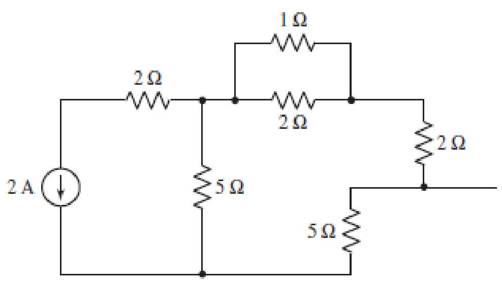
■ FIGURE 3.99
(a)
Find the number of nodes, number of loops and number of branches in the circuit.
Answer to Problem 63E
Number of nodes in the circuit is
Explanation of Solution
The circuit diagram is redrawn as shown in Figure 1.
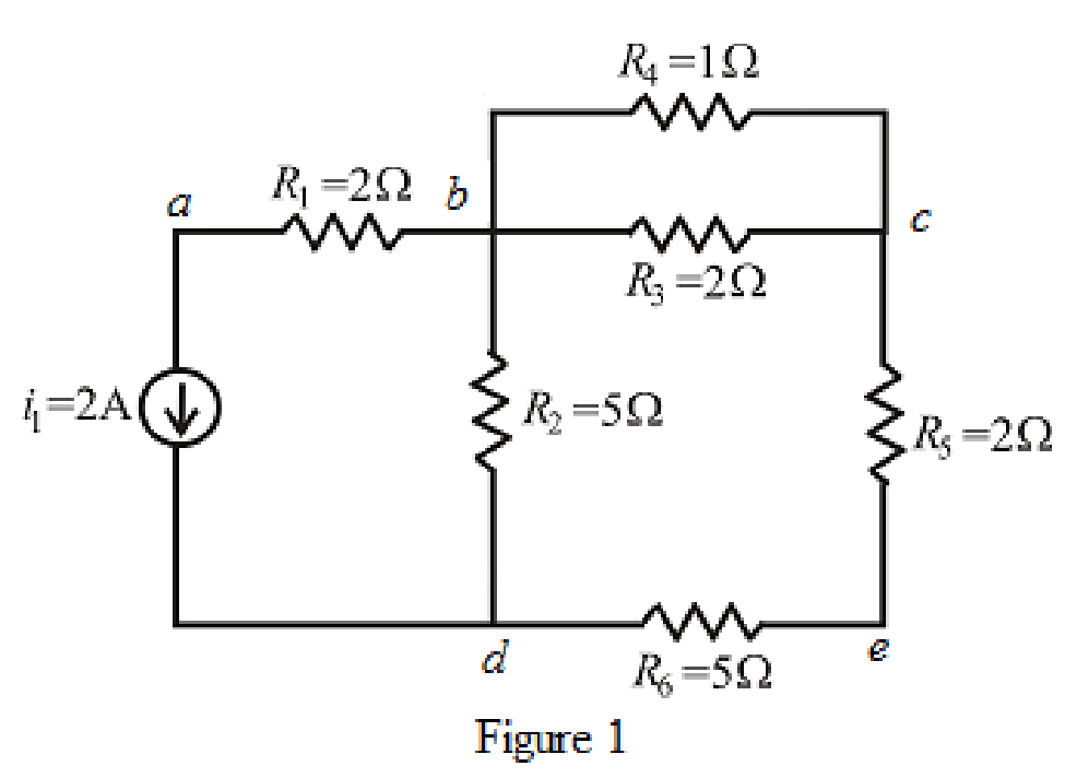
Refer to the redrawn Figure 1.
A point where two or more branches have common connection is known as node.
In Figure 1 two branches are connected at point
Each electrical element or device present in the circuit is known as branch.
There is
The circuit diagram is redrawn as shown in Figure 2,
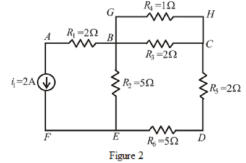
Refer to the redrawn Figure 2,
If starting and ending node is same for a path then it is known as closed path or loop.
Conclusion:
Thus, the number of nodes in the circuit is
(b)
Find the value of current through each resistor.
Answer to Problem 63E
The value of current through
Explanation of Solution
Formula used:
The expression for parallel combination of resistance is as follows.
Here,
Calculation:
The circuit diagram is redrawn as shown in Figure 3.
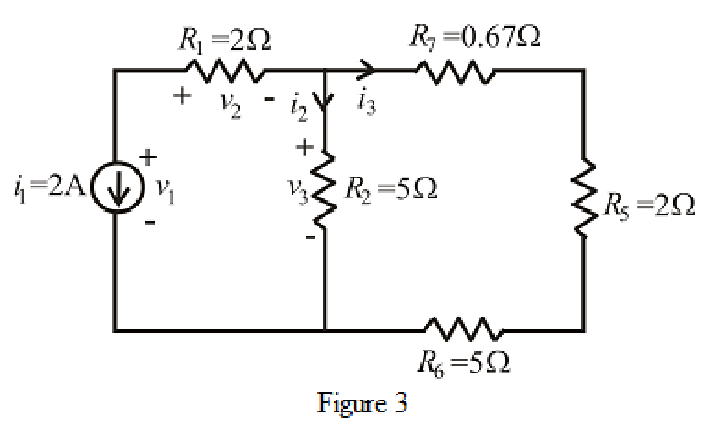
Refer to the redrawn Figure 3.
The expression for current
Here,
The expression for current
Here,
Refer to the redrawn Figure 1.
The expression for current
Here,
The expression for current
Here,
Refer to the redrawn Figure 1.
As
Rearrange for
Refer to the redrawn Figure 3.
As current source direction is downward means change sign of current means value of current is
Substitute
As resistor
So value of current through resistor
Substitute
So, the value of current through resistor
Refer to the redrawn Figure 1.
Substitute
So, the value of current through resistor
Substitute
So, the value of current through resistor
As resistor
Conclusion:
Thus, the value of current through
(c)
Find value of voltage across current source.
Answer to Problem 63E
The voltage across current source is
Explanation of Solution
Formula used:
The expression for voltage is as follows.
Here,
Calculation:
Refer to the redrawn Figure 3.
The expression for voltage
Here,
Refer to the redrawn Figure 3.
Substitute
So value of voltage
Substitute
So value of voltage
Substitute
Conclusion:
Thus, the voltage across current source is
Want to see more full solutions like this?
Chapter 3 Solutions
Loose Leaf for Engineering Circuit Analysis Format: Loose-leaf


- 7 Renewable Energy Sources are readily available everywhere, whole year round. Select one: True Falsearrow_forwardFor the network of Fig. 3: i) Draw the re model equivalent circuit. ii) Calculate IB, IC, and re.arrow_forwardengineering economics Valley Rendering, Inc. is considering purchasing a new flotation system for grease recovery. The company can finance a $150,000 system at 5% per year compound interest or 5.5% per year simple interest. If the total amount owed is due in a single payment at the end of 3 years, (a) which interest rate should the company select, and (b) how much is the difference in interest between the two schemes?arrow_forward
- Obtain the node voltages in the circuit of Fig. 3.4. Answer: v1=2 V, v2=14 V.arrow_forwardDesign a charger circuit for mobile phone from:a. 220V, 50Hz AC sourceb. 1.5 V AA BatterySelect the proper circuit topologies and components. (please explain in detail)arrow_forward3. For the network shown in Fig 3 below,a) Find the current through the middle 4 ohm resistor immediately after switch S is closed.b) Find the current through the inductor 0.2 s after switch S is closed.c) After a ‘very long’ time, the switch is then reopened. In this case, calculate the initial currentthrough the 8 ohm resistor.d) Find the current through the inductor 0.2 s after switch S is reopened.arrow_forward
- What is the relative degree of the system? Choose from the three plots below (a,b,c) what the corresponding root locus must look like for such a system, and explain your reasoning.arrow_forwardLesson: signals and systems Thanx for answer <3arrow_forward________ allows free will but within limits set by Allah a. None of the options b. Islam c. Christianity d. Buddhismarrow_forward
- Answer all 3arrow_forwardA resistive touch screen has 640 pixels in the x-direction and 1024pixels in the y-direction. The resistive grid has 8 V applied in both the xandy-directions. The pixel coordinates at the touch point are (480, 192).Calculate the voltages Vx and Vy.arrow_forwardDetermine the current labeled I3 in the circuit of Fig.3.55.arrow_forward
 Introductory Circuit Analysis (13th Edition)Electrical EngineeringISBN:9780133923605Author:Robert L. BoylestadPublisher:PEARSON
 Delmar's Standard Textbook Of ElectricityElectrical EngineeringISBN:9781337900348Author:Stephen L. HermanPublisher:Cengage Learning
 Programmable Logic ControllersElectrical EngineeringISBN:9780073373843Author:Frank D. PetruzellaPublisher:McGraw-Hill Education
 Fundamentals of Electric CircuitsElectrical EngineeringISBN:9780078028229Author:Charles K Alexander, Matthew SadikuPublisher:McGraw-Hill Education
 Electric Circuits. (11th Edition)Electrical EngineeringISBN:9780134746968Author:James W. Nilsson, Susan RiedelPublisher:PEARSON
 Engineering ElectromagneticsElectrical EngineeringISBN:9780078028151Author:Hayt, William H. (william Hart), Jr, BUCK, John A.Publisher:Mcgraw-hill Education,