
Concept explainers
Videos
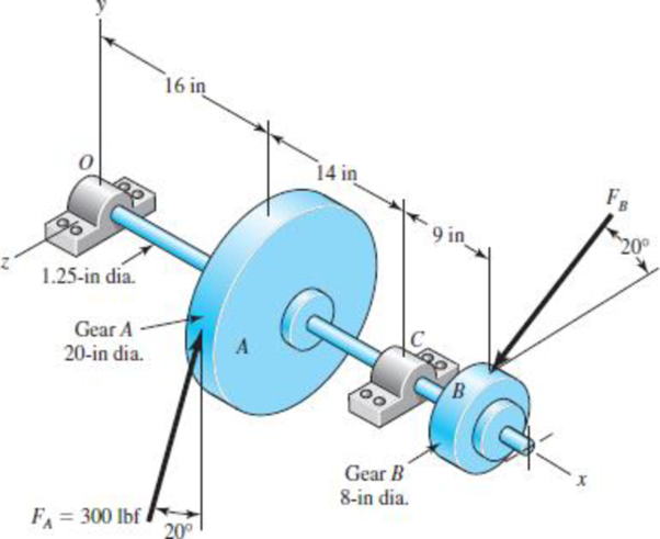
A gear reduction unit uses the countershaft shown in the figure. Gear A receives power from another gear with the transmitted force FA applied at the 20° pressure angle as shown. The power is transmitted through the shaft and delivered through gear B through a transmitted force FB at the pressure angle shown.
(a) Determine the force FB, assuming the shaft is running at a constant speed.
(b) Find the bearing reaction forces, assuming the bearings act as simple supports.
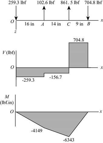
(c) Draw shear-force and bending-moment diagrams for the shaft. If needed, make one set for the horizontal plane and another set for the vertical plane.
(d) At the point of maximum bending moment, determine the bending stress and the torsional shear stress.
(e) At the point of maximum bending moment, determine the principal stresses and the maximum shear stress.
Problem 3–72*
(a)
The magnitude of the force acting on the wheel B.
Answer to Problem 72P
The magnitude of the force acting on the wheel B is
Explanation of Solution
The figure below shows the free body diagram of pulley A.
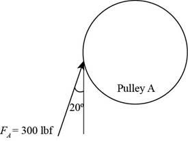
Figure-(1)
The figure below shows the free body diagram of pulley B.
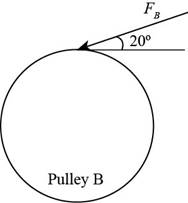
Figure-(2)
Calculate the force
Here, the force acting on pulley
Conclusion:
Substitute
Thus, the force
(b)
The bearing reaction forces at the supports.
Answer to Problem 72P
The bearing reaction at
Explanation of Solution
Write the expression for moment about bearing
Here, the reaction force at bearing
Write the equation to balance the forces in
Here, the reaction force at bearing
Write the expression for moment about bearing
Here, the reaction force at bearing
Write the equation to balance the forces in
Here, the reaction force at bearing
Calculate the reaction forces at bearing
Here, the reaction force at bearing
Calculate the reaction forces at bearing
Here, the reaction force at bearing
Conclusion:
Substitute
Substitute
Substitute
Substitute
Substitute
Thus, the bearing reaction at
Substitute
Thus, the bearing reaction force at
(c)
The shear force and bending moment diagram for the shaft.
Answer to Problem 72P
The shear force and bending moment diagram for the shaft in
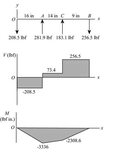
The shear force and bending moment diagram for the shaft in
Explanation of Solution
The calculations for shear force and bending moment diagram in
Calculate the shear force at
Here, the shear force at
Calculate the shear force at
Here, the shear force at
Calculate the shear force at
Here, the shear force at
Calculate the shear force at
Here, the shear force at
Calculate the moment at
Here, the moment at
Calculate the moment at
Here, the moment at
Calculate the moment at
Here, the moment at
Conclusion:
Substitute
Substitute
Substitute
Substitute
Substitute
Substitute
Thus, the shear force and bending moment diagram in
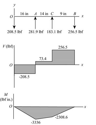
Figure-(3)
Substitute
Substitute
Substitute
Substitute
Substitute
Substitute
Thus, the shear force and bending moment diagram in
Figure-(4)
(d)
The bending stress at point of maximum bending moment.
The shear stress at point of maximum bending moment.
Answer to Problem 72P
The bending stress at point of maximum bending moment is
The shear stress at point of maximum bending moment is
Explanation of Solution
Write the net moment at
Here, the net moment at
Write the net moment at
Here, the net moment at
Write the torque transmitted by shaft from
Here, the torque transmitted by shaft from
Calculate the bending stress.
Here, the bending stress is
Calculate the shear stress.
Here, the shear stress is
Conclusion:
Substitute
Substitute
Since
Substitute
Substitute
Thus, the bending stress at point of maximum bending moment is
Substitute
Thus, the shear stress at point of maximum bending moment is
(e)
The principal stresses at point of maximum bending moment.
The maximum shear stress at point of maximum bending moment.
Answer to Problem 72P
The principal stresses at point of maximum bending moment are
The maximum shear stress at point of maximum bending moment is
Explanation of Solution
Calculate the maximum principal stress.
Here, the maximum principal stress is
Calculate the minimum principal stress.
Here, the minimum principal stress is
Calculate the maximum shear stress.
Here, maximum shear stress is
Conclusion:
Substitute
Substitute
Thus, the principal stresses at the point of maximum bending moment are
Substitute
Thus, the maximum shear stress at point of maximum bending moment is
Want to see more full solutions like this?
Chapter 3 Solutions
Shigley's Mechanical Engineering Design (McGraw-Hill Series in Mechanical Engineering)


- A bungee jumper having a mass of 55 kg leaps from a bridge, braking her fall with a long elastic shock cord having axial rigidity EA = 2.3 kN (see figure). If the jumpoff point is 60 m above the water, and if it is desired to maintain a clearance of 10 m between the jumper and the water, what length L of cord should be used?arrow_forward-19 The mechanical assembly shown in the figure consists of an aluminum tube, a rigid end plate, and two steel cables. The slack is removed from the cables by rotating the turnbuckles until the assembly is snug but with no initial stresses. Afterward, the turnbuckles are tightened by 1.5 turns. Calculate the forces in the tube and the cables and determine the shortening of the tube. As= 0.85 in2 for each cable, AA= 4.5 in2, L = 20 in., Es= 29,000 ksi, EA= 10,600 ksi, and p = 1/16 inarrow_forwardA spray nozzle for a garden hose requires under a water pressure force fp= 30 lb at C (see figure a force F = 5 lb to open the spring-loaded spray part c). Use dimensions given in figure part a chamber AB. The nozzle hand grip pivots about a (a) Find the force in the pin at O due to applied force F pin through a flange at O. Each of the two flanges force F has a thickness t = 1/16 in., and the pin has a diam- (b) Find average shear stress taver and bearing stress eter dp = 1/8 in. (see figure part a). The spray nozzle is attached to the garden hose with a quick release fitting at B (see figure part b). Three brass balls Find the average shear stress Ta,„ in the brass (diameter db= 3/16 in.) hold the spray head in place retaining balls al C due to water pressure Force fParrow_forward
- When drilling a hole in a table leg, a furniture maker uses a hand-operated drill (see figure) with a bit of diameter d = 4.0 mm. If the resisting torque supplied by the table leg is equal to 0.3 N · m, what is the maximum shear stress in the drill bit? If the allowable shear stress in the drill bit is 32 MPa, what is the maximum resisting torque before the drill binds up? If the shear modulus of elasticity of the steel is G = 75 GPa, what is the rate of twist of the drill bit (degrees per meter)?arrow_forwardA motor driving a solid circular steel shaft with diameter d = 1.5 in, transmits 50 hp to a gear at B, The allowable shear stress in the steel is 6000 psi. Calculate the required speed of rotation (number of revolutions per minute) so that the shear stress in the shaft does not exceed the allowable limit.arrow_forwardPipe 2 has been inserted snugly into Pipe I. but the holes Tor a connecting pin do not line up; there is a gap s. The user decides to apply either force P:lo Pipe I or force P-, to Pipe 2, whichever is smaller. Determine the following using the numerical properties in the box. (a) If only P{is applied, find Pt{tips} required to close gap s; if a pin is then inserted and Ptremoved, what are reaction forces RAand RBfor this load case? (b) If only P2is applied, find P2{kips) required to close gap a; if a pin is inserted and P2removed, what are reaction forces R^ and RBfor this load case? (c) What is the maximum shear stress in the pipes, for the loads in parts (a) and (b)? (d) If a temperature increase IT is to be applied to the entire structure to close gaps{instead of applying forces Ptand P2), find the AT required to close the gap. If a pin is inserted after the gaphas closed, what are reaction forces .''.', and RBfor this case? (e) Finally, if the structure (with pin inserted) then cools to the original ambient temperature, what are reaction forces Rtand Parrow_forward
- A bumper for a mine car is constructed with a spring of stiffness k = 1120 lb/in. (see figure). If a car weighing 3450 lb is traveling at velocity v = 7 mph when it strikes the spring, what is the maximum shortening of the spring?arrow_forwardRepeat Problem 3.3-1, but now use a circular tube with outer diameter d0= 2.5 in. and inner diameter di= 1.5 in.arrow_forwardSolve the preceding problem for W = 1.0 lb. h = 12 in.,and k =0.511,/in.arrow_forward
- A magnesium-alloy wire of diameter d = 4mm and length L rotates inside a flexible tube in order to open or close a switch from a remote location (see figure). A torque Tis applied manually (either clockwise or counterclockwise) at end 5, thus twisting the wire inside the tube. At the other end A, the rotation of the wire operates a handle that opens or closes the switch. A torque T0 = 0.2 N · m is required to operate the switch. The torsional stiffness of the tube, combined with friction between the tube and the wire, induces a distributed torque of constant intensity t = 0.04N m/m (torque per unit distance) acting along the entire length of the wire. (a) If the allowable shear stress in the wire is T allow = 30 MPa, what is the longest permissible length Lmaxof the wire?arrow_forwardTwo sections of steel drill pipe, joined by bolted flange plates at Ä are being tested to assess the adequacy of both the pipes. In the test, the pipe structure is fixed at A, a concentrated torque of 500 kN - m is applied at x = 0.5 m, and uniformly distributed torque intensity t1= 250 kN m/m is applied on pipe BC. Both pipes have the same inner diameter = 200 mm. Pipe AB has thickness tAB=15 mm, while pipe BC has thickness TBC= 12 mm. Find the maximum shear stress and maximum twist of the pipe and their locations along the pipe. Assume G = 75 GPa.arrow_forwardThe stepped shaft shown in the figure is required to transmit 600 kW of power at 400 rpm. The shaft has a full quarter-circular fillet, and the smaller diameter D1= 100 mm. If the allowable shear stress at the stress concentration is 100 MPa, at what diameter will this stress be reached? Is this diameter an upper or a lower limit on the value of D2?arrow_forward
 Mechanics of Materials (MindTap Course List)Mechanical EngineeringISBN:9781337093347Author:Barry J. Goodno, James M. GerePublisher:Cengage Learning