
Concept explainers
(a)
The free body diagram of the shaft.
The reactions at
(a)
Answer to Problem 75P
The free body-diagram of the shaft is as follows.

The reaction at
Explanation of Solution
The figure below shows the arrangement of shafts.
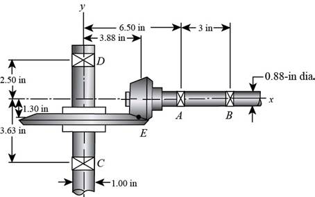
Figure (1)
The free body diagram of the shafts is shown below.
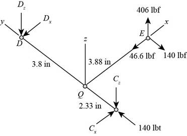
Figure (2)
Write the expression of moment at
Here, the reaction at
Write the expression of moment at
Here, the reaction at
Write the expression of moment at
Here, the reaction at
Write the expression of moment at
Write the expression of net force at
Here, the reaction at
Conclusion:
Substitute
Thus, the reaction at
Substitute
Thus, the reaction at
Substitute
Thus, the reaction at
Substitute
Thus, the reaction at
Substitute
Thus, the reaction at
(b)
The shear force and bending moment diagrams.
(b)
Answer to Problem 75P
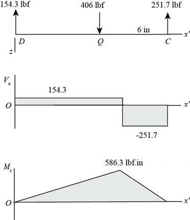
The figure below shows the shear force and bending moment diagram in

The figure below shows the shear force and bending moment diagram in
Explanation of Solution
It is clear from the free body diagram of the shaft
The calculations for shear force diagram in
Write the expression of Shear force at
Here, the shear at
Write the expression of Shear force at
Here, the shear force at
Write the expression of Shear force at
Here, the shear force at
The calculations for bending moment diagram in
We known that, the bending moment at the supports of the simply supported beam is zero.
Write the bending moment at
Here, the bending moment at
Write the expression of bending moment at
Here, the bending moment at
Write the expression of bending moment at
Here, the bending moment at
The calculations for shear force diagram in
Write the expression of Shear force at
Here, the shear at
Write the expression of Shear force at
Here, the shear force at
Write the expression of Shear force at
Here, the shear force at
We known that, the bending moment at the supports of the simply supported beam is zero.
Write the bending moment at
Here, the bending moment at
Write the expression of bending moment at
Here, the bending moment at
Conclusion:
Substitute
Substitute
Substitute
Substitute
Substitute
The figure below shows the shear force and bending moment diagram in
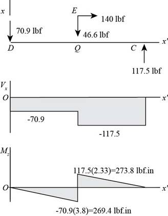
Figure (3)
Substitute
Substitute
Substitute
Substitute
The figure below shows the shear force and bending moment diagram in
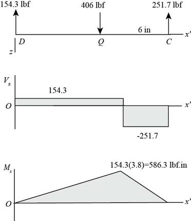
Figure (4)
(c)
The torsional shear stress for critical stress element.
The bending stress for critical stress element.
The axial stress for critical stress element.
(c)
Answer to Problem 75P
The torsional shear stress for critical stress element is
The bending stress for critical stress element is
The axial stress for critical stress element is
Explanation of Solution
It is clear from the bending moment diagram that the critical stress element is located at just right of
Write the expression of maximum torque acting on the shaft
Here, the maximum torque acting on the shaft
Write the expression of maximum bending moment acting on the shaft
Here, the maximum bending moment acting on the shaft
Write the expression of torsional shear stress for critical stress element.
Here, the torsional shear stress for critical stress element is
Write the expression of bending stress for critical stress element.
Here, the bending stress for critical stress element is
Write the expression of axial stress for critical stress element.
Here, the axial stress for critical stress element is
Conclusion:
Substitute
Substitute
Substitute
Thus, the torsional shear stress for critical stress element is
Substitute
Thus, the bending stress for critical stress element is
Substitute
Thus, the axial stress for critical stress element is
(d)
The principal stresses for critical stress element.
The maximum shear stress for critical stress element.
(d)
Answer to Problem 75P
The principal stresses for critical stress element are
The maximum shear stress for critical stress element is
Explanation of Solution
Write the expression of maximum bending stress on the critical stress element.
Here, the maximum bending stress on the critical stress element is
Write the expression of principal stresses on the critical stress element.
Here, the principal stresses on the critical stress element are
Write the expression of maximum shear stress on the critical stress element.
Here, the maximum shear stress on the critical stress element is
Conclusion:
Substitute
Substitute
Thus, the principal stresses for critical stress element are
Substitute
Thus, the maximum shear stress for critical stress element is
Want to see more full solutions like this?
Chapter 3 Solutions
Shigley's Mechanical Engineering Design (McGraw-Hill Series in Mechanical Engineering)


- A propeller shaft for a small yacht is made of a solid steel bar 104 mm in diameter. The allowable stress in shear is 48 MPa, and the allowable rate of twist is 2.0° in 3.5 meters. (a) Assuming that the shear modulus of elasticity is G = 80 GPa, determine the maximum torque that can be applied to the shaft. (b) Repeat part (a) if the shaft is now hollow with an inner diameter of 5d18. Compare values to corresponding values from part (a).arrow_forward.17 A mountain-bike rider going uphill applies torque T = Fd(F = l5lb, d = 4 in.) to the end of the handlebars ABCD by pulling on the handlebar extenders DE. Consider the right half of the handlebar assembly only (assume the bars are fixed at the fork at A). Segments AB and CD are prismatic with lengths L, = 2 in.andL3 = 8.5 in, and with outer diameters and thicknesses d01 = 1.25 in. 101 = 0.125 in. and d03 = O.87in.,i03 = 0.ll5in, respectively as shown. Segment BC’ of length L, = 1.2 in. however. is tapered, and outer diameter and thickness vary linearly between dimensions at B and C. Consider torsion effects only. Assume G = 4000 ksi is constant. Derive an integral expression for the angle of twist of half of the handlebar tube when it is subjected to torque T = Fd acting at the end. Evaluate ‘b1-, for the given numerical1ues.arrow_forwardThe stepped shaft shown in the figure is required to transmit 600 kW of power at 400 rpm. The shaft has a full quarter-circular fillet, and the smaller diameter D1= 100 mm. If the allowable shear stress at the stress concentration is 100 MPa, at what diameter will this stress be reached? Is this diameter an upper or a lower limit on the value of D2?arrow_forward
- A circular aluminum tube subjected to pure torsion by torques T(sec figure) has an outer radius r2equal to 1.5 times the inner radius r1. (a) If the maximum shear strain in the tube is measured as 400 × 10-6 rad, what is the shear strain y1at the inner surface? (b) If the maximum a1lo-abk rate of twist is 0.125 °/m and the maximum shear strain is to be kept at 400 × 10-6 rad by adjusting the torque T, that is the minimum required outer radius ( r2)Min?arrow_forwardTwo sections of steel drill pipe, joined by bolted flange plates at B, arc subjected to a concentrated torque 4000 kip-in. at x = 3 ft, and a uniformly distributed torque t0= 50 kip-ft/ft is applied on pipe BC. Let G = 11,800 ksi and assume that pipes AB and BC have the same inner diameter, d = 12 in. Pipe AB has a thickness tAB= 3/4 in., and pipe BC has a thickness tBC= 5/8 in. Find the reactive torques at A and C and the maximum shear stresses in each segment.arrow_forwardTwo sections of steel drill pipe, joined by bolted flange plates at Ä are being tested to assess the adequacy of both the pipes. In the test, the pipe structure is fixed at A, a concentrated torque of 500 kN - m is applied at x = 0.5 m, and uniformly distributed torque intensity t1= 250 kN m/m is applied on pipe BC. Both pipes have the same inner diameter = 200 mm. Pipe AB has thickness tAB=15 mm, while pipe BC has thickness TBC= 12 mm. Find the maximum shear stress and maximum twist of the pipe and their locations along the pipe. Assume G = 75 GPa.arrow_forward
- A hollow tube ABCDE constructed of monel metal is subjected to five torques acting in the directions shown in the figure. The magnitudes of the torques are T1= 1000 lb-in., T2= T4= 500 lb-in., and T3= T5= 800 lb-in. The tube has an outside diameter of d2= 1.0 in. The allowable shear stress is 12,000 psi and the allowable rate of twist is 2.0°/ft. Determine the maximum permissible inside diameter d1, of the tube.arrow_forwardSolve the preceding problem if the shaft has an outer diameter d2=150 mm and inner diameter d1= 100 mm. Also, the steel has a shear modulus of elasticity G = 75 GPa, and the applied torque is 16 kN ·m.arrow_forwardA stepped shaft ABC consisting of two solid, circular segments is subjected to torques T}and T2acting in opposite directions, as shown in the figure. The larger segment of the shaft has a diameter of dv- 2.25 in. and a length Lt= 30 in.; the smaller segment has a diameter d2— 1.75 in. and a length L, = 20 in. The torques are T, = 21,000 lb-in. and fz=10.000 lb-in. (a) Find reaction torque TAat support A. (b) Find the internal torque T(x) at two locations: x = L1/2 and x = L1+ L2/2. Show these internal torques on properly drawn free-body diagrams (FBDs).arrow_forward
- A tapered bar AB with a solid circular cross section is twisted by torques T = 36,000 lb-in. (sec figure). The diameter of the bar varies linearly from dAat the left-hand end to dBat the right-hand end. The bar has length L = 4,0 ft and is made of an aluminum alloy having shear modulus of elasticity G = 3.9 × 10⁶ psi. The allowable shear stress in the bar is 15,000 psi and the allowable angle of twist is 3.0°. If the diameter at end B is 1.5 times the diameter at end A, what is the minimum required diameter dAat end A?arrow_forwardA solid copper bar of circular cross section has length L = 1.25 m and shear modulus of elasticity G = 45 GPa. The bar is designed to carry a 250 N · m torque acting at the ends. If the allowable shear stress is 30 M Pa and the allowable angle of twist between the ends is 2.5°, what is the minimum required diameter?arrow_forwardA thin-walled rectangular tube has uniform thickness t and dimensions a x b to the median line of the cross section (see figure). How does the shear stress in the tube vary with the ratio = a/b if the total length Lmof the median line of the cross section and the torque T remain constant? From your results, show that the shear stress is smallest when the tube is square (ß = 1).arrow_forward
 Mechanics of Materials (MindTap Course List)Mechanical EngineeringISBN:9781337093347Author:Barry J. Goodno, James M. GerePublisher:Cengage Learning