
Videos
An open settling tank shown in the figure contains a liquid suspension. Determine the resultant force acting on the gate and its line of action if the liquid density is 850 kg/m3. The gate is parabolic as sketched, looking straight at the gate.
The Resultant force acting on gate and its line of action.
Answer to Problem 80P
The Resultant force acting on gate is
Explanation of Solution
Given:
Density of liquid is
Draw the cross-sectional view of the gate.
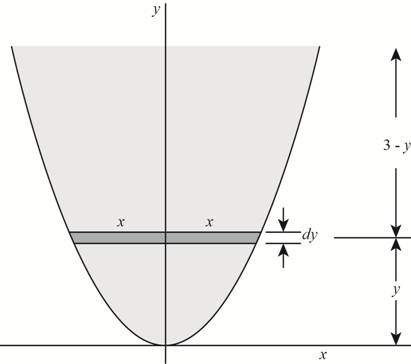
Figure (1)
Write the expression for the curve.
Here, horizontal axis is denoted by the x and vertical axis is denoted by the y.
Write the expression for the vertical distance between the centre of the elemental axis and the x axis.
Here, the vertical distance between the centre of the elemental axis and the x axis is
Write the expression for the area of the elemental strip.
Here, area is
Write the expression for the centre of gravity.
Here, centre of gravity is
Substitute
Draw a view of gate and liquid.
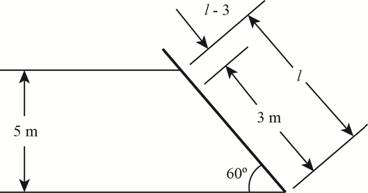
Figure (2)
Write the expression for the length of gate which is in contact with the liquid.
Here, length of the gate is
Write the expression for the centre of gravity of the gate from the free surface.
Here, the mass moment of inertia is
Write the expression for the vertical depth of the centre of gravity of gate from the free surface.
Here, the vertical depth of the centre of gravity of gate from the free surface is
Write the expression for pressure acing on the gate.
Here, pressure acing on the gate is
Write the expression for the area of gate resisting the pressure on the gate.
Here, the area of gate resisting the pressure on the gate is
Write the expression for the resultant force acting on the gate.
Here, the resultant force acting on the gate is
Write the expression for the moment of inertia.
Write the expression for the action of resultant hydrostatic force.
Here, the action of resultant hydrostatic force is
Write the expression for the centre of line of action from the free surface.
Here, the centre of line of action from the free surface is
Write the expression for the centre of location of the force from the bottom.
Here, the centre of location of the force from the bottom is
Calculation:
Substitute
Substitute
Substitute
Substitute
Substitute
Substitute
Substitute
Substitute
Substitute
Draw the diagram for different parameter.
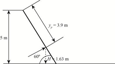
Figure (3)
Substitute
Substitute
Conclusion:
Resultant force acting on gate is
Want to see more full solutions like this?
Chapter 3 Solutions
Fluid Mechanics: Fundamentals and Applications


- Open tank (4.5 m long, 2.5 m height and 3 m wide) contains liquid (S-0.75) to height 1. m. If this tank is accelerated along its length on a horizontal truck at a constant value of 3.5 m/s, determine pressure at the bottom of the tank at front and rear edges (in kN/m). (take y=9.8 kN/m for water)arrow_forwardThe flow of water from a reservoir is controlled by an L-shaped gate hinged at point A, as shown in the figure. The mass of the weight at B (a = 4 m to the right of A, b = 3 m above the base) is 5125 kg. If the gate opens when the water height is 1.75 m above the base, determine the width (in meters, not showing) of the gate.arrow_forwardAn oil tanker 3m wide 2 m deep and 10 m long contains oil of density 800 kg/m3, if the tanker is closed and completely filled with the oil and accelerated horizontally at 3m/s2. a.) determine the total liquid thrust (hydrostatic force) on the front end. (in kN) b.) determine the total liquid thrust (hydrostatic force) on the rear end. (in kN)arrow_forward
- The bottom quarter of a vertical cylindrical tank of total height 0.4 m and diameter 0.3 m is filled with a liquid (SG > 1, like glycerin) and the rest with water, as shown in the figure. The tank is now rotated about its vertical axis at a constant angular speed of ω. Determine (a) the value of the angular speed when the point P on the axis at the liquid-liquid interface touches the bottom of the tank and (b) the amount of water that would be spilled out at this angular speed.arrow_forwardA 4-m-long quarter-circular gate of radius 4 m and of negligible weight is hinged about its upper edge A, as shown in the figure. The gate controls the flow of water over the ledge at B, where the gate is pressed by a spring. Determine the minimum spring force (in N) required to keep the gate closed when the water level rises to A at the upper edge of the gate.arrow_forwardIn the figure, the water level in a 1.8 m high and 0.9 diameter cylindrical tank is 1.4 m. If this tank is rotated with an angular velocity that can be inserted into the corner of its axis, the water in the tank will start to spill? Take the density of the water as 1000 kg / m3, the gravitational acceleration as 10 m / s2 and the value as 3.arrow_forward
- EMERGENCY!!!! The cover in the figure is hinged at the center O and has a fixed width w = 5 m. The equation of the surface is x = y2 / a (a = 3 m), the depth of the water to the right of the lid (D = 4 m). If the weight of the lid is neglected, it is necessary to keep the lid in balance. Find the size of the force (Fa) required, as shown. Take the density of the water as 999 kg / m3.arrow_forwardThe submerged sector gate AB shown in the figure is 1/9 of a circle of radius 4 m. The length of the gate is 10 m. Determine the horizontal component of water pressure acting on the gate.arrow_forwardAn inclined circular gate with water on one side is shown in the figure. Determine the resultant force acting on the gate and the location of the center of pressure.arrow_forward
- For the inverted manometer shown in the figure, all the fluid are at 20 0C. If PB - PA = 687 kPa, What must the height H be in cm. Take water density = 1000kg/m3 Mercury density = 13600kg/m3arrow_forwardA 3-m long (into the paper) rectangular gate AB (dimensions in the figure: a = 0.5 m, b = 1.2 m) is located at the bottom corner of a tank filled with water. Determine the net force (in kN, from the water pressure) acting on the gate in the horizontal (only) direction.arrow_forwardThe tank of water in Fig. is 12 cm wide into the paper.If the tank is accelerated to the right in rigid-body motion at6.0 m/s 2 , compute ( a ) the water depth on side AB and ( b ) thewater-pressure force on panel AB . Assume no spilling.arrow_forward
 International Edition---engineering Mechanics: St...Mechanical EngineeringISBN:9781305501607Author:Andrew Pytel And Jaan KiusalaasPublisher:CENGAGE L