
Videos
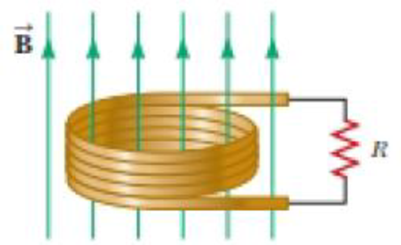
A circular coil enclosing an area of 100 cm2 is made of 200 turns of copper wire (Figure P30.31). The wire making up the coil has no resistance; the ends of the wire are connected across a 5.00-Ω resistor to form a closed circuit. Initially, a 1.10-T uniform magnetic field points perpendicularly upward through the plane of the coil. The direction of the field then reverses so that the final magnetic field has a magnitude of 1.10 T and points downward through the coil. If the time interval required for the field to reverse directions is 0.100 s, what is the average current in the coil during that interval?
Figure P30.31

Trending nowThis is a popular solution!

Chapter 30 Solutions
Physics for Scientists and Engineers with Modern Physics
Additional Science Textbook Solutions
The Physics of Everyday Phenomena
Life in the Universe (4th Edition)
Applied Physics (11th Edition)
Cosmic Perspective Fundamentals
Physics for Scientists and Engineers: A Strategic Approach with Modern Physics (4th Edition)
College Physics: A Strategic Approach (3rd Edition)


- In Figure P30.38, the rolling axle, 1.50 m long, is pushed along horizontal rails at a constant speed v = 3.00 m/s. A resistor R = 0.400 is connected to the rails at points a and b, directly opposite each other. The wheels make good electrical contact with the rails, so the axle, rails, and R form a closed-loop circuit. The only significant resistance in the circuit is R. A uniform magnetic field B = 0.080 0 T is vertically downward. (a) Find the induced current I in the resistor. (b) What horizontal force F is required to keep the axle rolling at constant speed? (c) Which end of the resistor, a or b, is at the higher electric potential? (d) What If? After the axle rolls past the resistor, does the current in R reverse direction? Explain your answer. Figure P30.38arrow_forwardA wire is bent in the form of a square loop with sides of length L (Fig. P30.24). If a steady current I flows in the loop, determine the magnitude of the magnetic field at point P in the center of the square. FIGURE P30.24arrow_forwardA long, straight wire carries a current given by I = Imax sin (t + ). The wire lies in the plane of a rectangular coil of N turns of wire as shown in Figure P30.45. The quantities Imax, , and are all constants. Assume Imax = 50.0 A, = 200 s1, N = 100, h = = 5.00 cm, and L = 20.0 cm. Determine the emf induced in the coil by the magnetic field created by the current in the straight wire. Figure P30.45arrow_forward
- Figure P30.39 shows a stationary conductor whose shape is similar to the letter e. The radius of its circular portion is a = 50.0 cm. It is placed in a constant magnetic field of 0.500 T directed out of the page. A straight conducting rod, 50.0 cm long, is pivoted about point O and rotates with a constant angular speed of 2.00 rad/s. (a) Determine the induced emf in the loop POQ. Note that the area of the loop is a2/2. (b) If all the conducting material has a resistance per length of 5.00 /m, what is the induced current in the loop POQ at the instant 0.250 s after point P passes point Q? Figure P30.39arrow_forwardA circular coil enclosing an area of 100 cm2 is made of 200 turns of copper wire (Figure P30.31). The wire making up the coil has no resistance; the ends of the wire are connected across a 5.00- resistor to form a closed circuit. Initially, a 1.10-T uniform magnetic field points perpendicularly upward through the plane of the coil. The direction of the field then reverses so that the final magnetic field has a magnitude of 1.10 T and points downward through the coil. If the time interval required for the field to reverse directions is 0.100 s, what is the average current in the coil during that interval? Figure P30.31arrow_forwardFigure P32.21 shows a circular conducting loop with a 5.00-cm radius and a total resistance of 1.30 placed within a uniform magnetic field pointing into the page. a. What is the rate at which the magnetic field is changing if a counterclockwise current I = 4.60 102 A is induced in the loop? b. Is the induced current caused by an increase or a decrease in the magnetic field with time?arrow_forward
- A metal rod of mass m slides without friction along two parallel horizontal rails, separated by a distance and connected by a resistor R, as shown in Figure P30.13. A uniform vertical magnetic field of magnitude B is applied perpendicular to the plane of the paper. The applied force shown in the figure acts only for a moment, to give the rod a speed v. In terms of m, , R, B, and v, find the distance the rod will then slide as it coasts to a stop. Figure P30.13arrow_forwardThe magnetic field through a square loop of wire with sides of length 3.00 cm changes with time as shown in Figure P32.8, where the sign indicates the direction of the field relative to the axis of the loop. Plot the emf induced in the loop versus time. FIGURE P32.8arrow_forwardReview. The bar of mass m in Figure P30.51 is pulled horizontally across parallel, frictionless rails by a massless string that passes over a light, frictionless pulley and is attached to a suspended object of mass M. The uniform upward magnetic field has a magnitude B, and the distance between the rails is . The only significant electrical resistance is the load resistor R shown connecting the rails at one end. Assuming the suspended object is released with the bar at rest at t = 0, derive an expression that gives the bars horizontal speed as a function of time. Figure P30.51arrow_forward
- A constant magnetic field of 0.275 T points through a circular loop of wire with radius 3.50 cm as shown in Figure P32.1. a. What is the magnetic flux through the loop? b. Is a current induced in the loop? Explain. FIGURE P32.1arrow_forwardA bar magnet is dropped through a loop of wire as shown in Figure P32.64. a. What is the direction of the induced current as the magnet is approaching the loop, as viewed from above where the magnet begins? b. What is the direction of the induced current after the magnet falls through and is receding from the loop, as viewed from above where the magnet began? FIGURE P32.64arrow_forwardA circular coil 15.0 cm in radius and composed of 145 tightly wound turns carries a current of 2.50 A in the counterclockwise direction, where the plane of the coil makes an angle of 15.0 with the y axis (Fig. P30.73). The coil is free to rotate about the z axis and is placed in a region with a uniform magnetic field given by B=1.35jT. a. What is the magnitude of the magnetic torque on the coil? b. In what direction will the coil rotate? FIGURE P30.73arrow_forward
 Physics for Scientists and EngineersPhysicsISBN:9781337553278Author:Raymond A. Serway, John W. JewettPublisher:Cengage Learning
 Physics for Scientists and Engineers with Modern ...PhysicsISBN:9781337553292Author:Raymond A. Serway, John W. JewettPublisher:Cengage Learning
 Physics for Scientists and Engineers: Foundations...PhysicsISBN:9781133939146Author:Katz, Debora M.Publisher:Cengage Learning
 Physics for Scientists and Engineers, Technology ...PhysicsISBN:9781305116399Author:Raymond A. Serway, John W. JewettPublisher:Cengage Learning
 Principles of Physics: A Calculus-Based TextPhysicsISBN:9781133104261Author:Raymond A. Serway, John W. JewettPublisher:Cengage Learning