
Videos
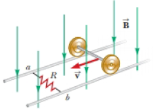
In Figure P30.38, the rolling axle, 1.50 m long, is pushed along horizontal rails at a constant speed v = 3.00 m/s. A resistor R = 0.400 Ω is connected to the rails at points a and b, directly opposite each other. The wheels make good electrical contact with the rails, so the axle, rails, and R form a closed-loop circuit. The only significant resistance in the circuit is R. A uniform magnetic field B = 0.080 0 T is vertically downward. (a) Find the induced current I in the resistor. (b) What horizontal force F is required to keep the axle rolling at constant speed? (c) Which end of the resistor, a or b, is at the higher electric potential? (d) What If? After the axle rolls past the resistor, does the current in R reverse direction? Explain your answer.
Figure P30.38

Trending nowThis is a popular solution!

Chapter 30 Solutions
Physics for Scientists and Engineers


- A loop of wire in the shape of a rectangle of width w and length L and a long, straight wire carrying a current I lie on a tabletop as shown in Figure P23.7. (a) Determine the magnetic flux through the loop due to the current I. (b) Suppose the current is changing with time according to I = a + bt, where a and b are constants. Determine the emf that is induced in the loop if b = 10.0 A/s, h = 1.00 cm, w = 10.0 cm, and L = 1.00 m. (c) What is the direction of the induced current in the rectangle? Figure P23.7arrow_forwardA metal rod of mass m slides without friction along two parallel horizontal rails, separated by a distance and connected by a resistor R, as shown in Figure P30.13. A uniform vertical magnetic field of magnitude B is applied perpendicular to the plane of the paper. The applied force shown in the figure acts only for a moment, to give the rod a speed v. In terms of m, , R, B, and v, find the distance the rod will then slide as it coasts to a stop. Figure P30.13arrow_forwardIn Figure P20.65 the rolling axle of length 1.50 m is pushed along horizontal rails at a constant speed v = 3.00 m/s. A resist or R = 0.400 is connected to the rails at points a and b, directly opposite each other. (The wheels make good electrical contact with the rails, so the axle, rails, and R form a closed-loop circuit. The only significant resistance in the circuit is R.) A uniform magnetic field B = 0.800 T is directed vertically downward. (a) Find the induced current I in the resistor. (b) What horizontal force F is required to keep the axle rolling at constant speed? (c) Which end of the resistor, a or b. is at the higher electric potential? (d) Alter the axle rolls past the resistor, does the current in R reverse direction? Explain your answer. Figure P20.65arrow_forward
- Figure P30.39 shows a stationary conductor whose shape is similar to the letter e. The radius of its circular portion is a = 50.0 cm. It is placed in a constant magnetic field of 0.500 T directed out of the page. A straight conducting rod, 50.0 cm long, is pivoted about point O and rotates with a constant angular speed of 2.00 rad/s. (a) Determine the induced emf in the loop POQ. Note that the area of the loop is a2/2. (b) If all the conducting material has a resistance per length of 5.00 /m, what is the induced current in the loop POQ at the instant 0.250 s after point P passes point Q? Figure P30.39arrow_forwardReview. The bar of mass m in Figure P30.51 is pulled horizontally across parallel, frictionless rails by a massless string that passes over a light, frictionless pulley and is attached to a suspended object of mass M. The uniform upward magnetic field has a magnitude B, and the distance between the rails is . The only significant electrical resistance is the load resistor R shown connecting the rails at one end. Assuming the suspended object is released with the bar at rest at t = 0, derive an expression that gives the bars horizontal speed as a function of time. Figure P30.51arrow_forwardFigure P32.21 shows a circular conducting loop with a 5.00-cm radius and a total resistance of 1.30 placed within a uniform magnetic field pointing into the page. a. What is the rate at which the magnetic field is changing if a counterclockwise current I = 4.60 102 A is induced in the loop? b. Is the induced current caused by an increase or a decrease in the magnetic field with time?arrow_forward
- A wire is bent in the form of a square loop with sides of length L (Fig. P30.24). If a steady current I flows in the loop, determine the magnitude of the magnetic field at point P in the center of the square. FIGURE P30.24arrow_forwardThe magnetic field through a square loop of wire with sides of length 3.00 cm changes with time as shown in Figure P32.8, where the sign indicates the direction of the field relative to the axis of the loop. Plot the emf induced in the loop versus time. FIGURE P32.8arrow_forwardConsider the apparatus shown in Figure P30.32: a conducting bar is moved along two rails connected to an incandescent lightbulb. The whole system is immersed in a magnetic field of magnitude B = 0.400 T perpendicular and into the page. The distance between the horizontal rails is = 0.800 m. The resistance of the lightbulb is R = 48.0 , assumed to be constant. The bar and rails have negligible resistance. The bar is moved toward the right by a constant force of magnitude F = 0.600 N. We wish to find the maximum power delivered to the lightbulb. (a) Find an expression for the current in the lightbulb as a function of B, , R, and v, the speed of the bar. (b) When the maximum power is delivered to the lightbulb, what analysis model properly describes the moving bar? (c) Use the analysis model in part (b) to find a numerical value for the speed v of the bar when the maximum power is being delivered to the lightbulb. (d) Find the current in the lightbulb when maximum power is being delivered to it. (e) Using P = I2R, what is the maximum power delivered to the lightbulb? (f) What is the maximum mechanical input power delivered to the bar by the force F? (g) We have assumed the resistance of the lightbulb is constant. In reality, as the power delivered to the lightbulb increases, the filament temperature increases and the resistance increases. Does the speed found in part (c) change if the resistance increases and all other quantities are held constant? (h) If so, does the speed found in part (c) increase or decrease? If not, explain. (i) With the assumption that the resistance of the lightbulb increases as the current increases, does the power found in part (f) change? (j) If so, is the power found in part (f) larger or smaller? If not, explain. Figure P30.32arrow_forward
- A conducting rod of length = 35.0 cm is free to slide on two parallel conducting bars as shown in Figure P30.35. Two resistors R1 = 2.00 and R2 = 5.00 are connected across the ends of the bars to form a loop. A constant magnetic field B = 2.50 T is directed perpendicularly into the page. An external agent pulls the rod to the left with a constant speed of v = 8.00 m/s. Find (a) the currents in both resistors, (b) the total power delivered to the resistance of the circuit, and (c) the magnitude of the applied force that is needed to move the rod with this constant velocity. Figure P30.35arrow_forwardWhy is the following situation impossible? A conducting rectangular loop of mass M = 0.100 kg, resistance R = 1.00 , and dimensions w = 50.0 cm by = 90.0 cm is held with its lower edge just above a region with a uniform magnetic field of magnitude B = 1.00 T as shown in Figure P30.34. The loop is released from rest. Just as the top edge of the loop reaches the region containing the field, the loop moves with a speed 4.00 m/s. Figure P30.34arrow_forwardA square loop with side length L, mass M, and resistance R lies in the xy plane. A magnetic field B = B0(y/L) k is present in the region of the space near the loop. Determine the magnitude and direction of the induced current in the loop as the loop starts moving at velocity v = B0(y/L) j.arrow_forward
 Physics for Scientists and Engineers with Modern ...PhysicsISBN:9781337553292Author:Raymond A. Serway, John W. JewettPublisher:Cengage Learning
 Physics for Scientists and EngineersPhysicsISBN:9781337553278Author:Raymond A. Serway, John W. JewettPublisher:Cengage Learning
 College PhysicsPhysicsISBN:9781305952300Author:Raymond A. Serway, Chris VuillePublisher:Cengage Learning
 Physics for Scientists and Engineers: Foundations...PhysicsISBN:9781133939146Author:Katz, Debora M.Publisher:Cengage Learning
 Principles of Physics: A Calculus-Based TextPhysicsISBN:9781133104261Author:Raymond A. Serway, John W. JewettPublisher:Cengage Learning