
Videos
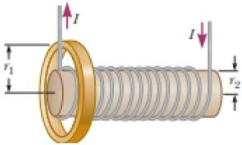
An aluminum ring of radius r1 = 5.00 cm and resistance 3.00 × 10⁻⁴ Ω is placed around one end of a long air-core solenoid with 1 000 turns per meter and radius r2 = 3.00 cm as shown in Figure P30.5. Assume the axial component of the field produced by the solenoid is one-half as strong over the area of the end of the solenoid as at the center of the solenoid. Also assume the solenoid produces negligible field outside its cross-sectional area. The current in the solenoid is increasing at a rate of 270 A/s. (a) What is the induced current in the ring? At the center of the ring, what are (b) the magnitude and (c) the direction of the magnetic field produced by the induced current in the ring?
Figure P30.5 Problems 5 and 6.
(a)
The induced current in the ring.
Answer to Problem 5P
The induced current in the ring is
Explanation of Solution
Given info: Radius of aluminum ring is
The magnetic field due to solenoid can be given as,
Here,
The area of the coil can be given as,
Here,
Substitute
The emf generated in the coil can be given as,
Here,
Substitute
Substitute
As the ring is placed around one end and also the field produced by the end of the solenoid is half at the centre of the solenoid.
Then, emf induced in the ring can be given as,
Here,
Substitute
The current induced in the ring can be given as,
Here,
Substitute
Thus, the current induced in the ring is
Conclusion:
Therefore, the current induced in the ring is
(b)
The magnitude of the magnetic field at the centre of the ring.
Answer to Problem 5P
The magnitude of the magnetic field at the centre of the ring is
Explanation of Solution
Given info: Radius of aluminum ring is
The magnetic field at the center of the ring can be given as,
Here,
Substitute
Thus, the magnitude of the magnetic field is
Conclusion:
Therefore, the magnitude of the magnetic field at the center of ring is
(c)
The direction of magnetic field at the center of the ring.
Answer to Problem 5P
The direction of magnetic field at the center of the ring is towards the left.
Explanation of Solution
Given info: Radius of aluminum ring is
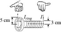
Figure (1)
The solenoid’s field points to the right through the ring as shown in the figure (I). So, to oppose the increasing field, the direction of magnetic field at the center of the ring will be towards the left.
Conclusion:
Therefore, the direction of magnetic field at the center of the ring will be towards towards the left.
Want to see more full solutions like this?
Chapter 30 Solutions
Physics for Scientists and Engineers with Modern Physics
Additional Science Textbook Solutions
Essential University Physics (3rd Edition)
Loose Leaf For Explorations: Introduction To Astronomy
MODERN PHYSICS (LOOSELEAF)
College Physics: A Strategic Approach (4th Edition)
An Introduction to Thermal Physics
Physics (5th Edition)


- A wire is bent in the form of a square loop with sides of length L (Fig. P30.24). If a steady current I flows in the loop, determine the magnitude of the magnetic field at point P in the center of the square. FIGURE P30.24arrow_forwardA long solenoid, with its axis along the x axis, consists of 200 turns per meter of wire that carries a steady current of 15.0 A. A coil is formed by wrapping 30 turns of thin wire around a circular frame that has a radius of 8.00 cm. The coil is placed inside the solenoid and mounted on an axis that is a diameter of the coil and coincides with the y axis. The coil is then rotated with an angular speed of 4.00 rad/s. The plane of the coil is in the yz plane at t = 0. Determine the emf generated in the coil as a function of time.arrow_forwardA loop of wire in the shape of a rectangle of width w and length L and a long, straight wire carrying a current I lie on a tabletop as shown in Figure P23.7. (a) Determine the magnetic flux through the loop due to the current I. (b) Suppose the current is changing with time according to I = a + bt, where a and b are constants. Determine the emf that is induced in the loop if b = 10.0 A/s, h = 1.00 cm, w = 10.0 cm, and L = 1.00 m. (c) What is the direction of the induced current in the rectangle? Figure P23.7arrow_forward
- In Figure P30.38, the rolling axle, 1.50 m long, is pushed along horizontal rails at a constant speed v = 3.00 m/s. A resistor R = 0.400 is connected to the rails at points a and b, directly opposite each other. The wheels make good electrical contact with the rails, so the axle, rails, and R form a closed-loop circuit. The only significant resistance in the circuit is R. A uniform magnetic field B = 0.080 0 T is vertically downward. (a) Find the induced current I in the resistor. (b) What horizontal force F is required to keep the axle rolling at constant speed? (c) Which end of the resistor, a or b, is at the higher electric potential? (d) What If? After the axle rolls past the resistor, does the current in R reverse direction? Explain your answer. Figure P30.38arrow_forwardFigure P32.21 shows a circular conducting loop with a 5.00-cm radius and a total resistance of 1.30 placed within a uniform magnetic field pointing into the page. a. What is the rate at which the magnetic field is changing if a counterclockwise current I = 4.60 102 A is induced in the loop? b. Is the induced current caused by an increase or a decrease in the magnetic field with time?arrow_forwardA metal rod of mass m slides without friction along two parallel horizontal rails, separated by a distance and connected by a resistor R, as shown in Figure P30.13. A uniform vertical magnetic field of magnitude B is applied perpendicular to the plane of the paper. The applied force shown in the figure acts only for a moment, to give the rod a speed v. In terms of m, , R, B, and v, find the distance the rod will then slide as it coasts to a stop. Figure P30.13arrow_forward
- A square loop with side length L, mass M, and resistance R lies in the xy plane. A magnetic field B = B0(y/L) k is present in the region of the space near the loop. Determine the magnitude and direction of the induced current in the loop as the loop starts moving at velocity v = B0(y/L) j.arrow_forwardA long, straight wire carries a current given by I = Imax sin (t + ). The wire lies in the plane of a rectangular coil of N turns of wire as shown in Figure P30.45. The quantities Imax, , and are all constants. Assume Imax = 50.0 A, = 200 s1, N = 100, h = = 5.00 cm, and L = 20.0 cm. Determine the emf induced in the coil by the magnetic field created by the current in the straight wire. Figure P30.45arrow_forwardFigure P30.39 shows a stationary conductor whose shape is similar to the letter e. The radius of its circular portion is a = 50.0 cm. It is placed in a constant magnetic field of 0.500 T directed out of the page. A straight conducting rod, 50.0 cm long, is pivoted about point O and rotates with a constant angular speed of 2.00 rad/s. (a) Determine the induced emf in the loop POQ. Note that the area of the loop is a2/2. (b) If all the conducting material has a resistance per length of 5.00 /m, what is the induced current in the loop POQ at the instant 0.250 s after point P passes point Q? Figure P30.39arrow_forward
- A Figure P32.74 shows an N-turn rectangular coil of length a and width b entering a region of uniform magnetic field of magnitude Bout directed out of the page. The velocity of the coil is constant and is upward in the figure. The total resistance of the coil is R. What are the magnitude and direction of the magnetic force on the coil a. when only a portion of the coil has entered the region with the field, b. when the coil is completely embedded in the field, and c. as the coil begins to exit the region with the field?arrow_forwardA rectangular conducting loop with dimensions w = 32.0 cm and h = 78.0 cm is placed a distance a = 5.00 cm from a long, straight wire carrying current I = 7.00 A in the downward direction (Fig. P32.75). a. What is the magnitude of the magnetic flux through the loop? b. If the current in the wire is increased linearly from 7.00 A to 15.0 A in 0.230 s, what is the magnitude of the induced emf in the loop? c. What is the direction of the current that is induced in the loop during this time interval?arrow_forwardA helicopter (Fig. P30.11) has blades of length 3.00 m, extending out from a central hub and rotating at 2.00 rev/s. If the vertical component of the Earths magnetic field is 50.0 T, what is the emf induced between the blade tip and the center hub? Figure P30.11arrow_forward
 Physics for Scientists and Engineers with Modern ...PhysicsISBN:9781337553292Author:Raymond A. Serway, John W. JewettPublisher:Cengage Learning
 Principles of Physics: A Calculus-Based TextPhysicsISBN:9781133104261Author:Raymond A. Serway, John W. JewettPublisher:Cengage Learning
 Physics for Scientists and Engineers: Foundations...PhysicsISBN:9781133939146Author:Katz, Debora M.Publisher:Cengage Learning
 Physics for Scientists and EngineersPhysicsISBN:9781337553278Author:Raymond A. Serway, John W. JewettPublisher:Cengage Learning
 Physics for Scientists and Engineers, Technology ...PhysicsISBN:9781305116399Author:Raymond A. Serway, John W. JewettPublisher:Cengage Learning