Mechanics of Materials, 7th Edition
7th Edition
ISBN: 9780073398235
Author: Ferdinand P. Beer, E. Russell Johnston Jr., John T. DeWolf, David F. Mazurek
Publisher: McGraw-Hill Education
bartleby

Concept explainers

bartleby

Videos

Textbook Question
Book Icon
Chapter 3.10, Problem 150P

A hollow cylindrical shaft of length L, mean radius cm, and uniform thickness t is subjected to a torque of magnitude T. Consider, on the one hand, the values of the average shearing stress τave and the angle of twist ϕ obtained from the elastic torsion formulas developed in Secs. 3.1C and 3.2 and, on the other hand, the corresponding values obtained from the formulas developed in Sec. 3.10 for thin-walled shafts, (a) Show that the relative error introduced by using the thin-walled-shaft formulas rather than the elastic torsion formulas is the same for τave and ϕ and that the relative error is positive and proportional to the ratio t/cm·(b) Compare the percent error corresponding to values of the ratio t/cm of 0.1, 0.2, and 0.4.
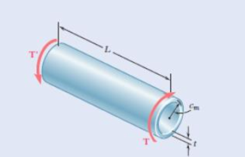
Chapter 3.10, Problem 150P, A hollow cylindrical shaft of length L, mean radius cm, and uniform thickness t is subjected to a

Fig. P3.150

(a)

Expert Solution
Check Mark
To determine

Show that the relative error introduced by using the thin walled shaft formulas rather than the elastic torsion formulas is the same for τave and ϕ and that the relative error is positive and proportional to the ratio (tcm).

Answer to Problem 150P

The ratio (τaveτm) is 1+14t2cm2_.

The ratio (ϕ2ϕ1) is 1+14t2cm2_.

Explanation of Solution

Given information:

The hollow cylindrical shaft of length is (L).

The uniform thickness of the hollow cylinder is (t).

The mean radius of the hollow cylinder is (cm).

The magnitude of torque is (T).

Calculation:

Writ the equation for outer radius (c1):

(c1)=cm+t2

Writ the equation for inner radius (c2):

(c2)=cmt2

Calculate the polar moment of inertia (J) using the relation:

J=π2(c24c14)=π2(c22+c12)(c2+c1)(c2c1)

Substitute cm+t2 for c1 and cmt2 for c2.

J=π2((cmt2)2+(cm+t2)2)((cmt2)+(cm+t2))((cmt2)(cm+t2))=π2(cm2+cmt+14t2+cm2cmt+14t2)(2cm)t=2π(cm2+14t2)cmt

Calculate the maximum shearing stress τm using the relation:

τm=TcmJ

Substitute 2π(cm2+14t2)cmt for J.

τm=Tcm2π(cm2+14t2)cmt=T2π(cm2+14t2)t

Calculate the angle twist (ϕ1) using the relation:

ϕ1=TLJG

Here, G is rigidity modulus.

Substitute 2π(cm2+14t2)cmt for J.

ϕ1=TL2π(cm2+14t2)cmtG

Write the expression to calculate the area bounded by centerline (a).

a=πcm2

Calculate the shearing stress at tube ‘a(τave) using the relation:

τave=T2ta

Substitute πcm2 for a.

τave=T2×t×πcm2=T2πtcm2

Calculate the angle twist (ϕ2) using the elastic torsion formula:

ϕ2=TL4a2Gdst

Substitute πcm2 for a.

ϕ2=TL4(πcm2)2Gdst=TL4(πcm2)2G(2πcmt)=TL2πcm3tG

Calculate the ratio (τaveτm):

Substitute T2πtcm2 for τave and T2π(cm2+14t2)t for τm.

(τaveτm)=(T2πtcm2)(T2π(cm2+14t2)t)=T2πtcm2×2π(cm2+14t2)tT=1+14t2cm2

Calculate the ratio (ϕ2ϕ1):

Substitute TL2πcm3tG for ϕ2 and TL2π(cm2+14t2)cmtG for ϕ1.

(ϕ2ϕ1)=(TL2πcm3tG)(TL2π(cm2+14t2)cmtG)=TL2πcm3tG×2π(cm2+14t2)cmtGTL=1+14t2cm

Thus, the ratio (τaveτm) is 1+14t2cm2_.

Thus, the ratio (ϕ2ϕ1) is 1+14t2cm2_.

(b)

Expert Solution
Check Mark
To determine

Compare the percent error corresponding to value of the ratio (tcm) of 0.1,0.2 and 0.4.

Answer to Problem 150P

The ratio (tcm) of 0.1, 0.2 and 0.4 are 0.25%,1.0%_, and 4.0%_ respectively.

Explanation of Solution

Calculation:

Calculate the percent error corresponding to value of the ratio (tcm) of 0.1,0.2 and 0.4:

(τaveτm)=(ϕ2ϕ1)

Substitute 1+14t2cm2 for τaveτm and 1+14t2cm2 for ϕ2ϕ1.

(τaveτm1)=(ϕ2ϕ11)=14t2cm2 (1).

Calculate the ratio for value 0.1 using the Equation (1).

Substitute 0.1 for (tcm).

14t2cm2=14(0.1)2=0.0025=0.0025×100%=0.25%

Calculate the ratio for value 0.2 using the Equation (1).

Substitute 0.2 for (tcm).

14t2cm2=14(0.2)2=0.01=0.01×100%=1.0%

Calculate the ratio for value 0.3 using the Equation (1).

Substitute 0.3 for (tcm).

14t2cm2=14(0.3)2=0.04=0.04×100%=4.0%

Thus, the ratio (tcm) of 0.1, 0.2 and 0.4 are 0.25%,1.0%_, and 4.0%_ respectively.

Want to see more full solutions like this?

Subscribe now to access step-by-step solutions to millions of textbook problems written by subject matter experts!
Students have asked these similar questions
The stepped shaft shown rotates at 480 rpm. Knowing that r = 0.2 in. and using figure 3.28, determine the largest torque T that can be transmitted without exceeding an allowable shearing stress of 7000 psi.
200 HP is delivered by a solid circular shaft at 1000 rpm rotational speed. If a hollow shaft is used having an inside diameter equal to the diameter of the solid shaft, determine what must be the outside diameter of this shaft if the angular twist of the hollow and solid shaft is to be equal? The allowable maximum shearing stress is 20,000 psi.
The preliminary design of a motor-to-generator connection calls for the use of a large hollow shaft with inner and outer diameters of 4 in. and 6 in., respectively. Knowing that the allowable shearing stress is 12 ksi, determine the maximum torque that can be transmitted by (a) the shaft as designed, (b) a solid shaft of the same weight, and (c) a hollow shaft of the same weight and an 8-in. outer diameter.

Chapter 3 Solutions

Mechanics of Materials, 7th Edition

Ch. 3.1 - Fig. P3.11 and P3.12 3.12 Knowing that an...Ch. 3.1 - Under normal operating conditions, the electric...Ch. 3.1 - In order to reduce the total mass of the assembly...Ch. 3.1 - The allowable shearing stress is 15 ksi in the...Ch. 3.1 - The allowable shearing stress is 15 ksi in the...Ch. 3.1 - The solid shaft shown is formed of a brass for...Ch. 3.1 - Solve Prob. 3.17 assuming that the direction of Tc...Ch. 3.1 - The solid rod AB has a diameter dAB= 60 mm and is...Ch. 3.1 - Fig. P3.19 and P3.20 3.20 The solid rod AB has a...Ch. 3.1 - A torque of magnitude T = 1000 N m is applied at D...Ch. 3.1 - Fig. P3.21 and P3.22 3.22 A torque of magnitude T...Ch. 3.1 - Under normal operating conditions a motor exerts a...Ch. 3.1 - Fig P3.23 and P3.24 3.24 Under normal operating...Ch. 3.1 - Prob. 25PCh. 3.1 - Fig. P3.25 and P3.26 3.26 The two solid shafts are...Ch. 3.1 - For the gear train shown, the diameters of the...Ch. 3.1 - Fig. P3.27 and P3.28 3.28 A torque T = 900 N m is...Ch. 3.1 - Fig. P3.29 3.29 While the exact distribution of...Ch. 3.1 - Fig. P3.30 3.30 (a) For a given allowable shearing...Ch. 3.3 - Determine the largest allowable diameter of a...Ch. 3.3 - The ship at A has just started to drill for oil on...Ch. 3.3 - (a) For the solid steel shaft shown, determine the...Ch. 3.3 - (a) For the aluminum pipe shown (G = 27 GPa),...Ch. 3.3 - The electric motor exerts a 500 N m-torque on the...Ch. 3.3 - The torques shown are exerted on pulleys and B....Ch. 3.3 - The aluminum rod BC (G = 26 GPa) is bonded to the...Ch. 3.3 - The aluminum rod AB (G = 27 GPa) is bonded to the...Ch. 3.3 - The solid spindle AB has a diameter ds = 1.75 in....Ch. 3.3 - Fig. p3.39 and p3.40 3.40 The solid spindle AB has...Ch. 3.3 - Two shafts, each of 78in. diameter, are connected...Ch. 3.3 - Two solid steel shafts each of 30-mm diameter, are...Ch. 3.3 - A coder F, used to record in digital form the...Ch. 3.3 - Fig. p3.43 3.44 For the gear train described in...Ch. 3.3 - The design specifications of a 1.2-m-long solid...Ch. 3.3 - 3.46 and 3.47 The solid cylindrical rod BC of...Ch. 3.3 - 3.46 and 3.47 The solid cylindrical rod BC of...Ch. 3.3 - The design of the gear-and-shaft system shown...Ch. 3.3 - The electric motor exerts a torque of 900 Nm on...Ch. 3.3 - A hole is punched at A in a plastic sheet by...Ch. 3.3 - The solid cylinders AB and BC are bonded together...Ch. 3.3 - Solve Prob. 3.51, assuming that cylinder AB is...Ch. 3.3 - The composite shaft shown consists of a...Ch. 3.3 - Fig. p3.53 and p3.54 3.54 The composite shaft...Ch. 3.3 - Two solid steel shafts (G = 77.2 GPa) are...Ch. 3.3 - Solve Prob. 3.55, assuming that the shaft AB is...Ch. 3.3 - 3.57 and 3.58 Two solid steel shafts are fitted...Ch. 3.3 - 3.57 and 3.58 Two solid steel shafts are fitted...Ch. 3.3 - The steel jacket CD has been attached to the...Ch. 3.3 - A torque T is applied as shown to a solid tapered...Ch. 3.3 - Prob. 61PCh. 3.3 - A solid shaft and a hollow shaft are made of the...Ch. 3.3 - An annular plate of thickness t and modulus G is...Ch. 3.5 - Determine the maximum shearing stress in a solid...Ch. 3.5 - Determine the maximum shearing stress in a solid...Ch. 3.5 - Using an allowable shearing stress of 4.5 ksi,...Ch. 3.5 - Using an allowable shearing stress of 50 MPa,...Ch. 3.5 - While a steel shaft of the cross section shown...Ch. 3.5 - Determine the required thickness of the 50-mm...Ch. 3.5 - A steel drive shaft is 6 ft long and its outer and...Ch. 3.5 - The hollow steel shaft shown (G = 77.2 GPa, all =...Ch. 3.5 - A steel pipe of 3.5-in. outer diameter is to be...Ch. 3.5 - 3.73 The design of a machine element calls for a...Ch. 3.5 - Three shafts and four gears are used to form a...Ch. 3.5 - Three shafts and four gears are used to form a...Ch. 3.5 - The two solid shafts and gears shown are used to...Ch. 3.5 - Fig. P3.76 and P3.77 3.77 The two solid shafts and...Ch. 3.5 - The shaft-disk-belt arrangement shown is used to...Ch. 3.5 - A 5-ft-long solid steel shaft of 0.875-in....Ch. 3.5 - A 2.5-m-long steel shaft of 30-mm diameter rotates...Ch. 3.5 - The design specifications of a 1.2-m-long solid...Ch. 3.5 - A 1.5-m-long tubular steel shaft (G = 77.2 GPa) of...Ch. 3.5 - Fig. P3.82 and P3.83 3.83 A 1.5-m-long tubular...Ch. 3.5 - The stepped shaft shown must transmit 40 kW at a...Ch. 3.5 - The stepped shaft shown rotates at 450 rpm....Ch. 3.5 - Knowing that the stepped shaft shown transmits a...Ch. 3.5 - The stepped shaft shown must rotate at a frequency...Ch. 3.5 - Fig. P3.87 and P3.88 3.88 The stepped shaft shown...Ch. 3.5 - A torque of magnitude T = 200 lbin. is applied to...Ch. 3.5 - Fig. P3.89, P3.90 and P3.91 3.90 In the stepped...Ch. 3.5 - In the stepped shaft shown, which has a full...Ch. 3.8 - The solid circular shaft shown is made of a steel...Ch. 3.8 - Prob. 93PCh. 3.8 - Prob. 94PCh. 3.8 - Prob. 95PCh. 3.8 - Fig. P3.95 and P3.96 3.96 The solid shaft shown is...Ch. 3.8 - It is observed that a straightened paper clip can...Ch. 3.8 - The solid shaft shown is made of a mild steel that...Ch. 3.8 - Prob. 99PCh. 3.8 - Prob. 100PCh. 3.8 - Prob. 101PCh. 3.8 - Prob. 102PCh. 3.8 - Prob. 103PCh. 3.8 - Prob. 104PCh. 3.8 - A solid circular rod is made of a material that is...Ch. 3.8 - Prob. 106PCh. 3.8 - Prob. 107PCh. 3.8 - Prob. 108PCh. 3.8 - Prob. 109PCh. 3.8 - Prob. 110PCh. 3.8 - Prob. 111PCh. 3.8 - A 50-mm diameter cylinder is made of a brass for...Ch. 3.8 - Prob. 113PCh. 3.8 - The solid circular drill rod AB is made of a steel...Ch. 3.8 - Prob. 115PCh. 3.8 - Prob. 116PCh. 3.8 - After the solid shaft of Prob. 3.116 has been...Ch. 3.8 - The hollow shaft shown is made of a steel that is...Ch. 3.8 - Prob. 119PCh. 3.8 - Prob. 120PCh. 3.10 - Determine the smallest allowable square cross...Ch. 3.10 - Prob. 122PCh. 3.10 - Using all = 70 MPa and G = 27 GPa, determine for...Ch. 3.10 - Prob. 124PCh. 3.10 - Determine the largest torque T that can be applied...Ch. 3.10 - Each of the two brass bars shown is subjected to a...Ch. 3.10 - Prob. 127PCh. 3.10 - Prob. 128PCh. 3.10 - Prob. 129PCh. 3.10 - Shafts A and B are made of the same material and...Ch. 3.10 - Prob. 131PCh. 3.10 - Shafts A and B are made of the same material and...Ch. 3.10 - Prob. 133PCh. 3.10 - Prob. 134PCh. 3.10 - Prob. 135PCh. 3.10 - A 36-kipin. torque is applied to a 10-ft-long...Ch. 3.10 - A 4-m-long steel member has a W310 60 cross...Ch. 3.10 - Prob. 138PCh. 3.10 - A 5-kipft torque is applied to a hollow aluminum...Ch. 3.10 - A torque T = 750 kNm is applied to the hollow...Ch. 3.10 - A 750-Nm torque is applied to a hollow shaft...Ch. 3.10 - 3.142 and 3.143 A hollow member having the cross...Ch. 3.10 - A hollow member having the cross section shown is...Ch. 3.10 - A 90-Nm torque is applied to a hollow shaft having...Ch. 3.10 - 3.145 and 3.146 A hollow member having the cross...Ch. 3.10 - 3.145 and 3.146 A hollow member having the cross...Ch. 3.10 - A cooling tube having the cross section shown is...Ch. 3.10 - A hollow cylindrical shaft was designed to have a...Ch. 3.10 - Equal torques are applied to thin-walled tubes of...Ch. 3.10 - A hollow cylindrical shaft of length L, mean...Ch. 3 - A steel pipe of 12-in. outer diameter is...Ch. 3 - A torque of magnitude T = 120 Nm is applied to...Ch. 3 - Fig. P3.152 3.153 Two solid shafts are connected...Ch. 3 - Prob. 154RPCh. 3 - Prob. 155RPCh. 3 - A torque of magnitude T = 4 kNm is applied at end...Ch. 3 - Ends A and D of the two solid steel shafts AB and...Ch. 3 - As the hollow steel shaft shown rotates at 180...Ch. 3 - Prob. 159RPCh. 3 - Prob. 160RPCh. 3 - Prob. 161RPCh. 3 - The shaft AB is made of a material that is...
Knowledge Booster
Background pattern image
Mechanical Engineering
Learn more about
Need a deep-dive on the concept behind this application? Look no further. Learn more about this topic, mechanical-engineering and related others by exploring similar questions and additional content below.
Similar questions
SEE MORE QUESTIONS
Recommended textbooks for you
Text book image
Elements Of Electromagnetics
Mechanical Engineering
ISBN:9780190698614
Author:Sadiku, Matthew N. O.
Publisher:Oxford University Press
Text book image
Mechanics of Materials (10th Edition)
Mechanical Engineering
ISBN:9780134319650
Author:Russell C. Hibbeler
Publisher:PEARSON
Text book image
Thermodynamics: An Engineering Approach
Mechanical Engineering
ISBN:9781259822674
Author:Yunus A. Cengel Dr., Michael A. Boles
Publisher:McGraw-Hill Education
Text book image
Control Systems Engineering
Mechanical Engineering
ISBN:9781118170519
Author:Norman S. Nise
Publisher:WILEY
Text book image
Mechanics of Materials (MindTap Course List)
Mechanical Engineering
ISBN:9781337093347
Author:Barry J. Goodno, James M. Gere
Publisher:Cengage Learning
Text book image
Engineering Mechanics: Statics
Mechanical Engineering
ISBN:9781118807330
Author:James L. Meriam, L. G. Kraige, J. N. Bolton
Publisher:WILEY
Understanding Torsion; Author: The Efficient Engineer;https://www.youtube.com/watch?v=1YTKedLQOa0;License: Standard YouTube License, CC-BY