
Videos
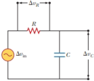
You have decided to build your own speaker system for your home entertainment system. The system will consist of two loudspeakers: a large “woofer,” to which you want to send low audio frequencies (bass), and a small “tweeter,” which should receive high audio frequencies (treble). To separate the high and low frequencies of the audio signal, you build the “crossover network” shown in Figure P32.45. The input voltage is the audio output of the amplifier in your system, shown in the figure as an AC source. You have two outputs as shown: one across the resistor and one across the capacitor. (a) Across which element should you connect the woofer? (b) Across which element should you connect the tweeter? (c) To choose the appropriate values of R and C, you need to determine an expression for the ratio of the output voltage to the input voltage as a function of angular frequency ω for the resistor as an output. (d) You need to determine a similar expression for the ratio of the output voltage to the input voltage as a function of angular frequency ω for the capacitor as an output.
Figure P32.45
Want to see the full answer?
Check out a sample textbook solution
Chapter 32 Solutions
Physics for Scientists and Engineers


- An PLC series circuit with R=600 , L = 30 mH. and c=0.050F is driven by an ac source whose frequency and voltage amplitude are 500 Hz and 50 V, respectively, (a) What is the impedance of the circuit? (b) What is the amplitude of the current in the circuit? (c) What is the phase angle between the emf of the source and the current?arrow_forwardAn RLC series circuit has an impedance of 60 and a power factor of 0.50, with the voltage Lagging the current (a) Should a capacitor or an inductor be placed in series with the elements to raise the power factor of the circuit? (b) What is the value of the capacitance or self-inductance that will raise the power factor to unity?arrow_forwardThe resistor in Figure P32.49 represents the midrange speaker in a three-speaker system. Assume its resistance to be constant at 8.00 . The source represents an audio amplifier producing signals of uniform amplitude Vmax = 10.0 V at all audio frequencies. The inductor and capacitor are to function as a band-pass filter with Vout/Vin=12 at 200 Hz and at 4.00 103 Hz. Determine the required values of (a) L and (b) C. Find (c) the maximum value of the ratio Vout/Vin; (d) the frequency fo at which the ratio has its maximum value; (e) the phase shift between vin and vout at 200 Hz, at fo, and at 4.00 103 Hz; and (f) the average power transferred to the speaker at 200 Hz, at f0, and at 4.00 103 Hz. (g) Recognizing that the diagram represents an RLC circuit driven by an AC source, find its quality factor. Figure P32.49arrow_forward
- You have decided to build your own speaker system for your home entertainment system. The system will consist of two loudspeakers: a large woofer, to which you want to send low audio frequencies (bass), and a small tweeter, which should receive high audio frequencies (treble). To separate the high and low frequencies of the audio signal, you build the crossover network shown in Figure P32.45. The input voltage is the audio output of the amplifier in your system, shown in the figure as an AC source. You have two outputs as shown: one across the resistor and one across the capacitor. (a) Across which element should you connect the woofer? (b) Across which element should you connect the tweeter? (c) To choose the appropriate values of R and C, you need to determine an expression for the ratio of the output voltage to the input voltage as a function of angular frequency for the resistor as an output. (d) You need to determine a similar expression for the ratio of the output voltage to the input voltage as a function of angular frequency for the capacitor as an output. Figure P32.45arrow_forwardA 20 resistor, 50F capacitor, and 30-mH inductor are connected in series with an ac source of amplitude 10 V and frequency 125 Hz. (a) What is the impedance of the circuit? (b) What is the amplitude of the current in the circuit? (c) What is the phase constant of the current? Is it leading or lagging the source voltage? (d) Write voltage drops across the resistor, capacitor, and inductor and the source voltage as a function of time, (e) What is the power factor of the circuit? (f) How much energy is used by the resistor in 2.5 s?arrow_forwardA sinusoidal voltage Δv = 35.0 sin(100t), where Δv is in volts and t is in seconds, is applied to a series RLC circuit with L = 180 mH, C = 99.0 µF, and R = 67.0 Ω. (a)What is the impedance (in Ω) of the circuit? Ω (b)What is the maximum current (in A)? A (c)Determine the numerical value for ? (in rad/s) in the equation i = Imax sin(?t − ?). rad/s (d)Determine the numerical value for ? (in rad) in the equation i = Imax sin(?t − ?). rad (e)What If? For what value of the inductance (in H) in the circuit would the current lag the voltage by the same angle ? as that found in part (d)? H (f)What would be the maximum current (in A) in the circuit in this case? Aarrow_forward
- A 60.0-Ω resistor is connected in series with a 30.0-µF capacitor and a generator having a maximum voltage of 1.20 × 10² V and operating at 60.0 Hz. Find the (a) capacitive reactance of the circuit, (b) impedance of the circuit, and (c) maximum current in the circuit. (d) Does the voltage lead or lag the current? (e) How will putting an inductor in series with the existing capacitor and resistor affect the current? Explain.arrow_forwardA sinusoidal voltage Δv = 35.0 sin(100t), where Δv is in volts and t is in seconds, is applied to a series RLC circuit with L = 180 mH, C = 99.0 µF, and R = 67.0 Ω. (a) What is the impedance (in Ω) of the circuit? (b)What is the maximum current (in A)? (c)Determine the numerical value for ? (in rad/s) in the equation i = Imax sin(?t − ?).rad/s (d)Determine the numerical value for ? (in rad) in the equation i = Imax sin(?t − ?). rad (e) What If? For what value of the inductance (in H) in the circuit would the current lag the voltage by the same angle ? as that found in part (d)? H (f)What would be the maximum current (in A) in the circuit in this case? please fill the whole thing thank you.arrow_forwardAn RLC series circuit has a 2.7 Ω resistor, a 125 μH inductor, and a 85 μF capacitor. (a) If the voltage source supplies an rms voltage of 5.7 V, what is the circuit’s rms current, in amperes, at a frequency of 3.5 kHz? (b) What is the resonant frequency, in kilohertz, of the circuit? (c) What is the rms current, Irms, in amperes, at resonance?arrow_forward
- In an oscillating LC circuit in which C = 4.5 μF, the maximum potential difference across the capacitor during the oscillations is 1.5 V and the maximum current through the inductor is 52.8 mA. What are (a) the inductance L and (b) the frequency of the oscillations? (c) How much time is required for the charge on the capacitor to rise from zero to its maximum value?arrow_forwardA sinusoidal voltage Δv = 35.0 sin(100t), where Δv is in volts and t is in seconds, is applied to a series RLC circuit with L = 180 mH, C = 99.0 µF, and R = 62.0 Ω. (a) What is the impedance (in Ω) of the circuit? (b) What is the maximum current (in A)? (c)Determine the numerical value for ? (in rad/s) in the equation i = Imax sin(?t − ?).arrow_forwardAn RLC series circuit with R = 600 Ω, L = 30 mH,and C = 0.050µF is driven by an ac source whosefrequency and voltage amplitude are 500 Hz and 50 V,respectively. (a) What is the impedance of the circuit? (b)What is the amplitude of the current in the circuit? (c) Whatis the phase angle between the emf of the source and the current?arrow_forward
 Physics for Scientists and Engineers with Modern ...PhysicsISBN:9781337553292Author:Raymond A. Serway, John W. JewettPublisher:Cengage Learning
 Physics for Scientists and EngineersPhysicsISBN:9781337553278Author:Raymond A. Serway, John W. JewettPublisher:Cengage Learning
 Physics for Scientists and Engineers: Foundations...PhysicsISBN:9781133939146Author:Katz, Debora M.Publisher:Cengage Learning