
Physics for Scientists and Engineers with Modern Physics
10th Edition
ISBN: 9781337553292
Author: Raymond A. Serway, John W. Jewett
Publisher: Cengage Learning
expand_more
expand_more
format_list_bulleted
Videos
Textbook Question
Chapter 32.4, Problem 32.4QQ
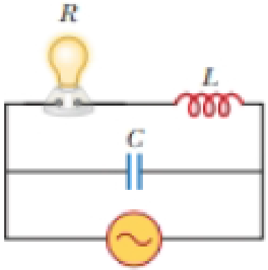
Consider the AC circuit in Figure 32.12. The frequency of the AC source is adjusted while its voltage amplitude is held constant. When does the lightbulb glow the brightest? (a) It glows brightest at high frequencies. (b) It glows brightest at low frequencies. (c) The brightness is the same at all frequencies.
Expert Solution & Answer

Trending nowThis is a popular solution!

Students have asked these similar questions
In the circuit of Figure P31.29, the battery emf is 50.0 V, the resistance is 250 V, and the capacitance is 0.500 ?F. The switch S is closed for a long time interval, and zero potential difference is measured across the capacitor. After the switch is opened, the potential difference across the capacitor reaches a maximum value of 150 V. What is the value of the inductance?
What are (a) the capacitive reactance, (b) the inductive reactance, (c) the impedance, (d) the current amplitude, and (e) the phase difference between the current and the emf of the generator? If known that the output of an ac generator connected to an RLC series combination has a frequency of 200 Hz and an amplitude of 0.100 V. Values for elements in circuit:R = 4.00 Ω, L = 3.00 × 10⁻³H, and C = 8.00 × 10⁻⁴F.
In an oscillating LC circuit, L = 25.0 mH and C = 7.80 mF. At time t 0 the current is 9.20 mA, the charge on the capacitor is 3.80 mC, and the capacitor is charging.What are (a) the total energy in the circuit, (b) the maximum charge on the capacitor, and (c) the maximum current? (d) If the charge on the capacitor is given by q = Q cos(vt + f), what is the phase angle f? (e) Suppose the data are the same, except that the capacitor is discharging at t = 0.What then is f?
Chapter 32 Solutions
Physics for Scientists and Engineers with Modern Physics
Ch. 32.2 - Consider the voltage phasor in Figure 32.4, shown...Ch. 32.3 - Consider the AC circuit in Figure 32.8. The...Ch. 32.4 - Consider the AC circuit in Figure 32.11. The...Ch. 32.4 - Consider the AC circuit in Figure 32.12. The...Ch. 32.5 - Label each part of Figure 32.16, (a), (b), and...Ch. 32.6 - Prob. 32.6QQCh. 32.7 - Prob. 32.7QQCh. 32 - (a) What is the resistance of a lightbulb that...Ch. 32 - A certain lightbulb is rated at 60.0 W when...Ch. 32 - The current in the circuit shown in Figure P32.3...
Ch. 32 - Figure P32.4 shows three lightbulbs connected to a...Ch. 32 - Prob. 5PCh. 32 - Prob. 6PCh. 32 - Prob. 7PCh. 32 - Prob. 8PCh. 32 - An AC source has an output rms voltage of 78.0 V...Ch. 32 - Prob. 10PCh. 32 - Prob. 11PCh. 32 - An AC source with an output rms voltage of 86.0 V...Ch. 32 - What is the maximum current in a 2.20-F capacitor...Ch. 32 - Prob. 14PCh. 32 - In addition to phasor diagrams showing voltages...Ch. 32 - An AC source with Vmax = 150 V and f = 50.0 Hz is...Ch. 32 - You are working in a factory and have been tasked...Ch. 32 - Prob. 18PCh. 32 - Prob. 19PCh. 32 - A 60.0-ft resistor is connected in series with a...Ch. 32 - A series RLC circuit has a resistance of 45.0 and...Ch. 32 - Prob. 22PCh. 32 - Prob. 23PCh. 32 - An AC voltage of the form v = 90.0 sin 350t, where...Ch. 32 - Prob. 25PCh. 32 - A series RLC circuit has components with the...Ch. 32 - You wish to build a series RLC circuit for a...Ch. 32 - A 10.0- resistor, 10.0-mH inductor, and 100-F...Ch. 32 - Prob. 29PCh. 32 - The primary coil of a transformer has N1 = 350...Ch. 32 - Prob. 31PCh. 32 - A transmission line that has a resistance per unit...Ch. 32 - Prob. 33APCh. 32 - Prob. 34APCh. 32 - Prob. 35APCh. 32 - Prob. 36APCh. 32 - Prob. 37APCh. 32 - Prob. 38APCh. 32 - Prob. 39APCh. 32 - Prob. 40APCh. 32 - Prob. 41APCh. 32 - (a) Sketch a graph of the phase angle for an RLC...Ch. 32 - A series RLC circuit contains the following...Ch. 32 - Review. In the circuit shown in Figure P32.44,...Ch. 32 - You have decided to build your own speaker system...Ch. 32 - Prob. 46APCh. 32 - Prob. 47APCh. 32 - A series RLC circuit in which R = l.00 , L = 1.00...Ch. 32 - The resistor in Figure P32.49 represents the...Ch. 32 - Prob. 50CPCh. 32 - Prob. 51CP
Knowledge Booster


Learn more about
Need a deep-dive on the concept behind this application? Look no further. Learn more about this topic, physics and related others by exploring similar questions and additional content below.Similar questions
- In a purely inductive AC circuit as shown in Figure P32.6, Vmax = 100 V. (a) The maximum current is 7.50 A at 50.0 Hz. Calculate the inductance L. (b) What If? At what angular frequency is the maximum current 2.50 A? Figure P32.6 Problem 6 and 7.arrow_forwardAn ac source of voltage amplitude 10 V delivers electric energy at a rate of 0.80 W when its current output is 2.5 A. What is the phase angle between the emf and the current?arrow_forwardA 1.5k resistor and 30-mH inductor are connected in series, as below, across a120-V(rms)ac power source oscillating at 60-Hz frequency. (a) Find the current in the circuit. (b) Find the voltage drops across the resistor and inductor. (C) Find the impedance of the circuit. (d) Find the power dissipated in the resistor. (e) Find the power dissipated in the inductor. (1) Find the power produced by the source.arrow_forward
- Consider the Filter circuit shown in Figure P33.56. (a) Show that the ratio of the amplitude of the output voltage to that of the input voltage is to that of input voltage is VoutVin=1/CR2+(1C)2 (b) What value does this ratio approach as the frequency decreases toward zero? (c) What value does this ratio approach as the frequency increases without limit? (d) At what frequency is the ratio equal to one-half?arrow_forwardAn inductor and a resistor are connected in series across an AC source as in Figure OQ33.1. Immediately after the switch is closed, which of the following statements is true? (a) The current in the circuit is V/R. (b) The voltage across the inductor is zero, (c) The current in the circuit is zero, (d) The voltage across the resistor is V (e) The voltage across the inductor is half its maximum value.arrow_forwardSuppose a 0.55 mH inductor is connected to a 37.5 μF capacitor. Find the resonant frequency, in hertz. The simple AC circuit shown on the right has resistance R = 47.5 Ω and impedance Z = 165 Ω. The rms voltage of the power supply is ΔVrms = 196 V. (a) Express the rms current, Irms, in terms of ΔVrms and Z. (b) Calculate the numerical value of Irms in amps. (c) Express the average power dissipated in the circuit, Pavg, in terms of Irms and R. (d) Calculate the value of Pavg, in watts.arrow_forward
- A resistor ( R = 9.00 × 10² Ω), a capacitor (C = 0.250 µF), and an inductor (L = 2.50 H) are connected in series across a 2.40 × 10²-Hz AC source for which ΔV max = 1.40 × 10² V. Calculate (a) the impedance of the circuit, (b) the maximum current delivered by the source, and (c) the phase angle between the current and voltage. (d) Is the current leading or lagging the voltage?arrow_forwardIn a purely inductive AC circuit as shown in the figure, ΔVmax = 100 V. A square circuit is shown. On its left side is an AC source of voltage ΔVmax sin(2?ft). On the right side of the loop is an inductor of inductance L. (a) The maximum current is 8.70 A at 55.0 Hz. Calculate the inductance L. (b) At what angular frequency ? is the maximum current 2.40 A?arrow_forwardA 1.0-kHz AC generator that is connected to a certain capacitor has an rms voltage of 2.0 V, and an rms current of 0.45 mA flows through the circuit. What is the reactance of the capacitor? What is the capacitance of the capacitor? [Answers: (a) Xc = 4.4 × 10³ Ω, (b) C = 3.6 × 10⁻⁸ F]arrow_forward
- VP30.10.3 The sum of the electrical and magnetic energies in an L-C circuit is 0.800 J. At a certain instant the energy is exactly half electrical and half magnetic, the capacitor charge is 5.30 mC, and the current is 8.00 A. Find (a) the capacitance, (b) the inductance, and (c) the angular frequency of oscillation.arrow_forwardVP31.3.3 An ac circuit includes a 155 Ω resistor in series with an 8.00 μF capacitor. The current in the circuit has amplitude 4.00×10⁻³ A. (a) Find the frequency for which the capacitive reactance equals the resistance. (b) At this frequency, what are the amplitudes of the voltages across the resistor and capacitor?arrow_forwardA particular inductor has appreciable resistance. When theinductor is connected to a 12 - V battery, the current in theinductor is 3.0 A. When it is connected to an AC source withan rms output of 12 V and a frequency of 60. Hz, the currentdrops to 2.0 A. What are (a) the impedance at 60. Hz and(b) the inductance of the inductor?arrow_forward
arrow_back_ios
SEE MORE QUESTIONS
arrow_forward_ios
Recommended textbooks for you
 Physics for Scientists and Engineers, Technology ...PhysicsISBN:9781305116399Author:Raymond A. Serway, John W. JewettPublisher:Cengage Learning
 Physics for Scientists and Engineers: Foundations...PhysicsISBN:9781133939146Author:Katz, Debora M.Publisher:Cengage Learning
 Physics for Scientists and EngineersPhysicsISBN:9781337553278Author:Raymond A. Serway, John W. JewettPublisher:Cengage Learning
 Physics for Scientists and Engineers with Modern ...PhysicsISBN:9781337553292Author:Raymond A. Serway, John W. JewettPublisher:Cengage Learning
Physics for Scientists and Engineers, Technology ...
Physics
ISBN:9781305116399
Author:Raymond A. Serway, John W. Jewett
Publisher:Cengage Learning
Physics for Scientists and Engineers: Foundations...
Physics
ISBN:9781133939146
Author:Katz, Debora M.
Publisher:Cengage Learning
Physics for Scientists and Engineers
Physics
ISBN:9781337553278
Author:Raymond A. Serway, John W. Jewett
Publisher:Cengage Learning
Physics for Scientists and Engineers with Modern ...
Physics
ISBN:9781337553292
Author:Raymond A. Serway, John W. Jewett
Publisher:Cengage Learning
Introduction To Alternating Current; Author: Tutorials Point (India) Ltd;https://www.youtube.com/watch?v=0m142qAZZpE;License: Standard YouTube License, CC-BY