
Physics for Scientists and Engineers: Foundations and Connections
1st Edition
ISBN: 9781133939146
Author: Katz, Debora M.
Publisher: Cengage Learning
expand_more
expand_more
format_list_bulleted
Videos
Textbook Question
Chapter 33, Problem 71PQ
Problems 71 and 72 paired.
Figure P33.71 shows a series RLC circuit with a 25.0-Ω resistor, a 430.0-mH inductor, and a 24.0-μF capacitor connected to an AC source with Vmax = 60.0 V operating at 60.0 Hz. What is the maximum voltage across the a. resistor, b. inductor, and c. capacitor in the circuit?
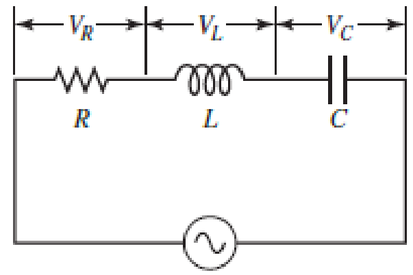
FIGURE P33.71 Problems 71 and 72.
Expert Solution & Answer

Trending nowThis is a popular solution!

Chapter 33 Solutions
Physics for Scientists and Engineers: Foundations and Connections
Ch. 33.1 - Prob. 33.1CECh. 33.1 - Prob. 33.2CECh. 33.2 - Prob. 33.3CECh. 33.3 - Prob. 33.4CECh. 33.4 - Prob. 33.5CECh. 33.5 - Prob. 33.6CECh. 33.7 - Prob. 33.7CECh. 33 - Prob. 1PQCh. 33 - Prob. 2PQCh. 33 - Prob. 3PQ
Ch. 33 - Prob. 4PQCh. 33 - Prob. 5PQCh. 33 - Prob. 6PQCh. 33 - Prob. 7PQCh. 33 - Prob. 8PQCh. 33 - Prob. 9PQCh. 33 - Prob. 10PQCh. 33 - Prob. 11PQCh. 33 - At one instant, a current of 6.0 A flows through...Ch. 33 - Prob. 13PQCh. 33 - Prob. 14PQCh. 33 - Prob. 15PQCh. 33 - In Figure 33.9A (page 1052), the switch is closed...Ch. 33 - Prob. 17PQCh. 33 - Prob. 18PQCh. 33 - Prob. 19PQCh. 33 - Prob. 20PQCh. 33 - Prob. 21PQCh. 33 - Prob. 22PQCh. 33 - In the LC circuit in Figure 33.11, the inductance...Ch. 33 - A 2.0-F capacitor is charged to a potential...Ch. 33 - Prob. 26PQCh. 33 - Prob. 27PQCh. 33 - Prob. 28PQCh. 33 - For an LC circuit, show that the total energy...Ch. 33 - Prob. 30PQCh. 33 - Prob. 31PQCh. 33 - Prob. 32PQCh. 33 - Prob. 33PQCh. 33 - Suppose you connect a small lightbulb across a DC...Ch. 33 - Prob. 35PQCh. 33 - Prob. 36PQCh. 33 - Prob. 37PQCh. 33 - Prob. 38PQCh. 33 - Prob. 39PQCh. 33 - Prob. 40PQCh. 33 - Prob. 41PQCh. 33 - Prob. 42PQCh. 33 - Prob. 43PQCh. 33 - In an ideal AC circuit with capacitance, there is...Ch. 33 - Prob. 45PQCh. 33 - Prob. 46PQCh. 33 - Prob. 47PQCh. 33 - Prob. 48PQCh. 33 - Prob. 49PQCh. 33 - An AC generator with an rms emf of 15.0 V is...Ch. 33 - Prob. 51PQCh. 33 - Prob. 52PQCh. 33 - Prob. 53PQCh. 33 - Prob. 54PQCh. 33 - Prob. 55PQCh. 33 - Prob. 56PQCh. 33 - Prob. 57PQCh. 33 - Prob. 58PQCh. 33 - Prob. 59PQCh. 33 - An AC source of angular frequency is connected to...Ch. 33 - An RLC series circuit is constructed with R =...Ch. 33 - Prob. 62PQCh. 33 - A series RLC circuit driven by a source with an...Ch. 33 - Prob. 64PQCh. 33 - Prob. 65PQCh. 33 - Prob. 66PQCh. 33 - Prob. 67PQCh. 33 - Prob. 68PQCh. 33 - Prob. 69PQCh. 33 - Prob. 70PQCh. 33 - Problems 71 and 72 paired. Figure P33.71 shows a...Ch. 33 - Prob. 72PQCh. 33 - Prob. 73PQCh. 33 - Prob. 74PQCh. 33 - Prob. 75PQCh. 33 - In a series RLC circuit with a maximum current of...Ch. 33 - Prob. 77PQCh. 33 - Two coaxial cables of length with radii a and b...Ch. 33 - Prob. 79PQCh. 33 - Prob. 80PQCh. 33 - Prob. 81PQCh. 33 - Prob. 82PQCh. 33 - Prob. 83PQCh. 33 - Prob. 84PQ
Knowledge Booster


Learn more about
Need a deep-dive on the concept behind this application? Look no further. Learn more about this topic, physics and related others by exploring similar questions and additional content below.Similar questions
- An PLC series circuit with R=600 , L = 30 mH. and c=0.050F is driven by an ac source whose frequency and voltage amplitude are 500 Hz and 50 V, respectively, (a) What is the impedance of the circuit? (b) What is the amplitude of the current in the circuit? (c) What is the phase angle between the emf of the source and the current?arrow_forwardA 7.0-mH induct is connected across a 60-Hz ac source whose voltage amplitude is 50 V. (a) What is the maximum current through the inductor? (b) What is the phase relationship between the current through and the potential difference across the inductor?arrow_forwardA 20 resistor, 50F capacitor, and 30-mH inductor are connected in series with an ac source of amplitude 10 V and frequency 125 Hz. (a) What is the impedance of the circuit? (b) What is the amplitude of the current in the circuit? (c) What is the phase constant of the current? Is it leading or lagging the source voltage? (d) Write voltage drops across the resistor, capacitor, and inductor and the source voltage as a function of time, (e) What is the power factor of the circuit? (f) How much energy is used by the resistor in 2.5 s?arrow_forward
- An AC source operating at 60. Hz with a maximum voltage of 170 V is connected in series with a resistor (R = 1.2 k) and a capacitor (C = 2.5 F). (a) What is the maximum value of the current in the circuit? (b) What are the maximum values of the potential difference across the resistor and the capacitor? (c) When the current is zero, what are the magnitudes of the potential difference across the resistor, the capacitor, and the AC source? How much charge is on the capacitor at this instant? (d) When the current is at a maximum, what are the magnitudes of the potential differences across the resistor, the capacitor, and the AC source? How much charge is on the capacitor at this instant?arrow_forwardAn AC source operating at 60. Hz with a maximum voltage of 170 V is connected in series with a resistor (R = 1.2 k) and a capacitor (C = 2.5 F). (a) What is the maximum value of the current in the circuit? (b) What are the maximum values of the potential difference across the resistor and the capacitor? (c) When the current is zero, what are the magnitudes of the potential difference across the resistor, the capacitor, and the AC source? How much charge is on the capacitor at this instant? (d) When the current is at a maximum, what are the magnitudes of the potential differences across the resistor, the capacitor, and the AC source? How much charge is on the capacitor at this instant?arrow_forwardA capacitor and a resistor are connected in series across an AC source as shown in Figure OQ33.3. After the switch is closed, which of the following statements is true? (a) The voltage across the capacitor lags the current by 90. (b) The voltage across (lie resistor is out of phase with the current. (c) The voltage across the capacitor leads the current by 90. (d) The current decreases as the frequency of the source is increased, but its peak voltage remains the same. (e) None of those statements is correct.arrow_forward
- An inductor and a resistor are connected in series across an AC source as in Figure OQ33.1. Immediately after the switch is closed, which of the following statements is true? (a) The current in the circuit is V/R. (b) The voltage across the inductor is zero, (c) The current in the circuit is zero, (d) The voltage across the resistor is V (e) The voltage across the inductor is half its maximum value.arrow_forwardA resistor and inductor are connected in series across an ac generator. The emf of the generator is given by v(t)=V0cost , where V0=120V and =120rad/s ; also, R=400 and L = 1.5 H. (a) What Is the impedance of the circuit? (b) What is the amplitude of the current through the resistor? (C) Write an expression for the current through the resistor. (d) Write expressions representing the voltages across the resistor and across the inductor.arrow_forwardA series RLC circuit has resistance R = 50.0 and inductance L. = 0.500 H. (a) Find the circuits capacitance C if the voltage source operates at a frequency of f = 60.0 Hz and the impedance is Z = R = 50.0 . (b) What is the phase angle between the current and the voltage?arrow_forward
- An ac source of voltage amplitude 100 V and frequency 1.0 kHz drives an PLC series circuit with R=20, L = 4.0 mH, and C=50F . (a) Determine the rms current through the circuit, (b) What are the rms voltages across the three elements? (c) What is the phase angle between the emf and the current? (d) What is the power output of the source? (e) What is the power dissipated in the resistor?arrow_forwardIn the AC circuit shown in Figure P32.3, R = 70.0 and the output voltage of the AC source is Vmax sin t. (a) If VR = 0.250 Vmax for the first time at t = 0.0100 s, what is the angular frequency of the source? (b) What is the next value of t for which VR = 0.250 Vmax? Figure P32.6 Problem 3 and 5.arrow_forwardThe RC high-pass filter shown in Figure P33.53 has a resistance R = 0.500 and a capacitance C = 613 F. What is the ratio of the amplitude of the output voltage to that of the input voltage for this filter for a source frequency of 600 Hz?arrow_forward
arrow_back_ios
SEE MORE QUESTIONS
arrow_forward_ios
Recommended textbooks for you
 Physics for Scientists and Engineers: Foundations...PhysicsISBN:9781133939146Author:Katz, Debora M.Publisher:Cengage Learning
 Physics for Scientists and EngineersPhysicsISBN:9781337553278Author:Raymond A. Serway, John W. JewettPublisher:Cengage Learning
 Physics for Scientists and Engineers with Modern ...PhysicsISBN:9781337553292Author:Raymond A. Serway, John W. JewettPublisher:Cengage Learning
 College PhysicsPhysicsISBN:9781938168000Author:Paul Peter Urone, Roger HinrichsPublisher:OpenStax College
 Physics for Scientists and Engineers, Technology ...PhysicsISBN:9781305116399Author:Raymond A. Serway, John W. JewettPublisher:Cengage Learning
Physics for Scientists and Engineers: Foundations...
Physics
ISBN:9781133939146
Author:Katz, Debora M.
Publisher:Cengage Learning
Physics for Scientists and Engineers
Physics
ISBN:9781337553278
Author:Raymond A. Serway, John W. Jewett
Publisher:Cengage Learning
Physics for Scientists and Engineers with Modern ...
Physics
ISBN:9781337553292
Author:Raymond A. Serway, John W. Jewett
Publisher:Cengage Learning
College Physics
Physics
ISBN:9781938168000
Author:Paul Peter Urone, Roger Hinrichs
Publisher:OpenStax College
Physics for Scientists and Engineers, Technology ...
Physics
ISBN:9781305116399
Author:Raymond A. Serway, John W. Jewett
Publisher:Cengage Learning
Introduction To Alternating Current; Author: Tutorials Point (India) Ltd;https://www.youtube.com/watch?v=0m142qAZZpE;License: Standard YouTube License, CC-BY