
Concept explainers
Videos
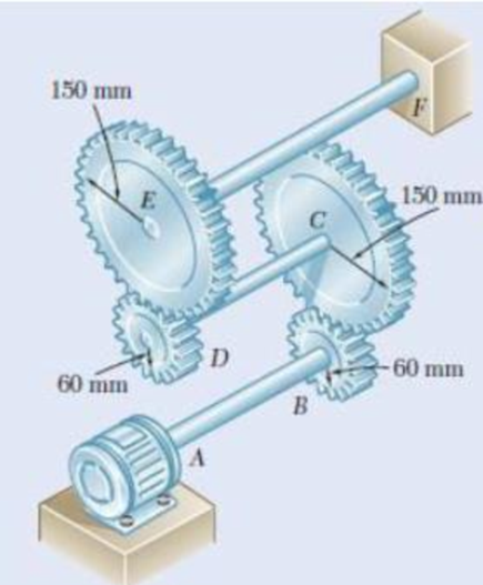
Three shafts and four gears are used to form a gear train that will transmit 7.5 kW from the motor at A to a machine tool at F. (Bearings for the shafts are omitted in the sketch.) Knowing that the frequency of the motor is 30 Hz and that the allowable stress for each shaft is 60 MPa, determine the required diameter of each shaft.
The required diameter of the shaft AB.
The required diameter of the shaft CD.
The required diameter of the shaft EF.
Answer to Problem 75P
The required diameter of the shaft AB is
The required diameter of the shaft CD is
The required diameter of the shaft EF is
Explanation of Solution
Given information:
The frequency of the motor is 30 Hz.
The power transmitted by the shafts is 7.5 kW.
The allowable shearing stress in each shaft is 60 MPa.
The diameter of the shaft AB is
The diameter of the shaft CD is
The diameter of the shaft EF is
Calculation:
The maximum shear stress in the shaft
Here, T is the torque transmitted by the shaft, c is the radius of the shaft, and J is the polar moment of inertia of the shaft.
The power transmitted by the shaft
Here, f is the frequency of the shaft.
For shaft AB:
The frequency of the shaft AB is
Substitute
The polar moment of inertia of shaft AB with radius
Substitute 60 MPa for
Diameter of the shaft AB is twice the radius of the shaft AB.
Therefore, the required diameter of the shaft AB is
For shaft CD:
The radius at gear B is
The radius at gear C is
The frequency of the shaft CD is as follows:
Substitute
The polar moment of inertia of shaft CD with radius
Substitute 60 MPa for
The diameter of the shaft CD is twice the radius of the shaft CD.
Therefore, the required diameter of the shaft CD is
For shaft EF:
The radius at gear D is
The radius at gear E is
The frequency of the shaft EF is as follows:
Substitute
The polar moment of inertia of shaft EF with radius
Substitute 60 MPa for
The diameter of the shaft EF is twice the radius of the shaft EF.
Therefore, the required diameter of the shaft EF is
Want to see more full solutions like this?
Chapter 3 Solutions
Mechanics of Materials, 7th Edition


- The design specifications for the gear-and-shaft system shown require that the same diameter be used for both shafts and that the angle through which pulley A will rotate when subjected to a 2-kip·in. torque TA while pulley D is held fixed will not exceed 7.5°. Determine the required diameter of the shafts if both shafts are made of a steel with G= 11.2 × 10⁶ psi and τall= 12 ksi.assuming that both shafts are made of a brass with G= 5.6 × 10⁶ psi and τall= 8 ksi.arrow_forwardTwo solid shafts are connected by the gears shown. Knowing thatG = 77 GPa for each shaft, determine the angle through which end A rotates when TA=1200 N·m.arrow_forwardA steel shaft must transmit 150 kW at a speed of 360 rpm. Knowing that G = 77.2 GPa, design a solid shaft so that the maximum shearing stress will not exceed 50 MPa and the angle of twist in a 2.8-m length must not exceed 3°. Consider the frequency f to be 6 Hz. The diameter of the solid shaft is -- mmarrow_forward
- For the assembly of Fig. , knowing that rA= 2rB, determine the angle of rotation of end E of shaft BE when the torque T is applied at Earrow_forwardA torque of 10kN-m is to be carried by a flanged bolt coupling that consists of eight 10mm diameter steel bolts on a circle of diameter 400mm and six 10mm diameter steel bolts on a circle of diameter 300mm. Determine the number of 10mm diameter steel bolts that must be used on the 400mm bolt circle of the coupling to increase the torque capacity to 15kN-m.arrow_forwardTwo shafts, each of 7878 -in. diameter, are connected by the gears shown. Knowing that G = 11.2 ×10⁶ psi and that the shaft at F is fixed, determine the angle through which end A rotates when a 1.4-kip·in. torque is applied at A.arrow_forward
- A hollow shaft's inner diameter is half of its outer diameter D. Show that the maximum torque that this shaft can carry is 15/16th of the maximum torque that a solid shaft of diameter D made of the same material can carry.arrow_forwardPlate gear C of this gear system are carried on the arm A and free to rotated. the pitch circle diameter of the internally toothed ring gear D is to be 214 mm and the module 4 mm. When the ring gear D is stationary, the arm A, which carries three planet wheels C of equal size, is to make one revolution in the same direction as the sun wheel B for every five revolutions of the driving spindle carrying the sunwheel B.Determine suitable number of teeth for all the wheels and the exact diameter of pitch circle of the ring.1.1.Calculate the number of teeth of the ring gear D.(3)1.2.State an equation tha relate the number of teeth of gear D, B and C.(1)1.3.Use the table method to calculate the number of teeth of gear B.(13)1.4.Calculate the number of teeth for gear C.arrow_forwardUnder normal operating conditions, the electric motor exerts a torque of 2.4 kN·m on shaft AB. Each shaft is solid with diameter d 52 mm. In order to reduce the total mass of the assembly, a new design is being considered in which the diameter of shaft BC will be smaller. Determine the smallest diameter of shaft BC for which the maximum value of the shearing stress in the assembly will not be increased. The smallest diameter of shaft BC is mm.arrow_forward
- For the bevel-gear system shown, determine the required value of α if the ratio of MB to MA is to be 3.arrow_forwardThe design specifications of a 2-m-long solid circular transmission shaft require that the angle of twist of the shaft not exceed 3° when a torque of 9 kN·m is applied. Determine the required diameter of the shaft, knowing that the shaft is made of (a) a steel with an allowable shearing stress of 90 MPa and a modulus of rigidity of 77 GPa, (b) a bronze with an allowable shearing stress of 35 MPa and a modulus of rigidity of 42 GPaarrow_forwardTwo shafts, each of 78-in.-diameter, are connected by the gears shown. Knowing that G= 11.2 ×10⁶ psi and that the shaft at F is fixed, deter-mine the angle through which end A rotates when a 1.2 kip·in.-torque is applied at A.arrow_forward
 Elements Of ElectromagneticsMechanical EngineeringISBN:9780190698614Author:Sadiku, Matthew N. O.Publisher:Oxford University Press
 Mechanics of Materials (10th Edition)Mechanical EngineeringISBN:9780134319650Author:Russell C. HibbelerPublisher:PEARSON
 Thermodynamics: An Engineering ApproachMechanical EngineeringISBN:9781259822674Author:Yunus A. Cengel Dr., Michael A. BolesPublisher:McGraw-Hill Education
 Control Systems EngineeringMechanical EngineeringISBN:9781118170519Author:Norman S. NisePublisher:WILEY
 Mechanics of Materials (MindTap Course List)Mechanical EngineeringISBN:9781337093347Author:Barry J. Goodno, James M. GerePublisher:Cengage Learning
 Engineering Mechanics: StaticsMechanical EngineeringISBN:9781118807330Author:James L. Meriam, L. G. Kraige, J. N. BoltonPublisher:WILEY