
Loose Leaf for Engineering Circuit Analysis Format: Loose-leaf
9th Edition
ISBN: 9781259989452
Author: Hayt
Publisher: Mcgraw Hill Publishers
expand_more
expand_more
format_list_bulleted
Concept explainers
Videos
Textbook Question
Chapter 3.8, Problem 16P
3.16 Use voltage division to determine vx in the circuit of Fig. 3.37.
(Don’t let the sinusoidal source throw you.)
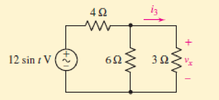
FIGURE 3.37
Expert Solution & Answer
Want to see the full answer?
Check out a sample textbook solution
Students have asked these similar questions
Obtain the node voltages in the circuit of Fig. 3.4.
Answer: v1=2 V, v2=14 V.
Lesson: signals and systems
Thanx for answer <3
In the circuit of Fig.3.60, it is determined that v1= 3V and v3 = 1.5 V. Calculate vR and V2
Chapter 3 Solutions
Loose Leaf for Engineering Circuit Analysis Format: Loose-leaf
Ch. 3.2 - 3.1 (a) Count the number of branches and nodes in...Ch. 3.3 - Determine ix and vx in the circuit of Fig. 3.7....Ch. 3.3 - For the circuit of Fig. 3.9, if vR1=1V, determine...Ch. 3.3 - Determine vx in the circuit of Fig. 3.11.Ch. 3.4 - In the circuit of Fig. 3.12b, vs1 = 120 V, vs2 =...Ch. 3.4 - 3.6 In the circuit of Fig. 3.14, find the power...Ch. 3.5 - Determine v in the circuit of Fig. 3.16.Ch. 3.5 - For the single-node-pair circuit of Fig. 3.18,...Ch. 3.6 - Determine the current i in the circuit of Fig....Ch. 3.6 - Determine the voltage v in the circuit of Fig....
Ch. 3.6 - Determine whether the circuit of Fig. 3.25...Ch. 3.7 - 3.12 Determine a single-value equivalent...Ch. 3.7 - 3.13 Determine i in the circuit of Fig. 3.29....Ch. 3.7 - Determine v in the circuit of Fig. 3.31 by first...Ch. 3.7 - 3.15 For the circuit of Fig. 3.33, calculate the...Ch. 3.8 - 3.16 Use voltage division to determine vx in the...Ch. 3.8 - In the circuit of Fig. 3.40, use resistance...Ch. 3 - Referring to the circuit depicted in Fig. 3.45,...Ch. 3 - Referring to the circuit depicted in Fig. 3.46,...Ch. 3 - For the circuit of Fig. 3.47: (a) Count the number...Ch. 3 - For the circuit of Fig. 3.47: (a) Count the number...Ch. 3 - Refer to the circuit of Fig. 3.48, and answer the...Ch. 3 - A local restaurant has a neon sign constructed...Ch. 3 - Referring to the single-node diagram of Fig. 3.50,...Ch. 3 - Determine the current labeled I in each of the...Ch. 3 - In the circuit shown in Fig. 3.52, the resistor...Ch. 3 - The circuit of Fig. 3.53 represents a system...Ch. 3 - In the circuit depicted in Fig. 3.54, ix is...Ch. 3 - For the circuit of Fig. 3.55 (which employs a...Ch. 3 - Determine the current labeled I3 in the circuit of...Ch. 3 - Study the circuit depicted in Fig. 3.57, and...Ch. 3 - Prob. 15ECh. 3 - For the circuit of Fig. 3.58: (a) Determine the...Ch. 3 - For each of the circuits in Fig. 3.59, determine...Ch. 3 - Use KVL to obtain a numerical value for the...Ch. 3 - Prob. 19ECh. 3 - In the circuit of Fig. 3.55, calculate the voltage...Ch. 3 - Determine the value of vx as labeled in the...Ch. 3 - Consider the simple circuit shown in Fig. 3.63....Ch. 3 - (a) Determine a numerical value for each current...Ch. 3 - The circuit shown in Fig. 3.65 includes a device...Ch. 3 - The circuit of Fig. 3.12b is constructed with the...Ch. 3 - Obtain a numerical value for the power absorbed by...Ch. 3 - Compute the power absorbed by each element of the...Ch. 3 - Compute the power absorbed by each element in the...Ch. 3 - Kirchhoffs laws apply whether or not Ohms law...Ch. 3 - Referring to the circuit of Fig. 3.70, (a)...Ch. 3 - Determine a value for the voltage v as labeled in...Ch. 3 - Referring to the circuit depicted in Fig. 3.72,...Ch. 3 - Determine the voltage v as labeled in Fig. 3.73,...Ch. 3 - Although drawn so that it may not appear obvious...Ch. 3 - Determine the numerical value for veq in Fig....Ch. 3 - Determine the numerical value for ieq in Fig....Ch. 3 - For the circuit presented in Fig. 3.76. determine...Ch. 3 - Determine the value of v1 required to obtain a...Ch. 3 - (a) For the circuit of Fig. 3.78, determine the...Ch. 3 - What value of IS in the circuit of Fig. 3.79 will...Ch. 3 - (a) Determine the values for IX and VY in the...Ch. 3 - Determine the equivalent resistance of each of the...Ch. 3 - For each network depicted in Fig. 3.82, determine...Ch. 3 - (a) Simplify the circuit of Fig. 3.83 as much as...Ch. 3 - (a) Simplify the circuit of Fig. 3.84, using...Ch. 3 - Making appropriate use of resistor combination...Ch. 3 - Calculate the voltage labeled vx in the circuit of...Ch. 3 - Determine the power absorbed by the 15 resistor...Ch. 3 - Calculate the equivalent resistance Req of the...Ch. 3 - Show how to combine four 100 resistors to obtain...Ch. 3 - Prob. 51ECh. 3 - Prob. 52ECh. 3 - Prob. 53ECh. 3 - Prob. 54ECh. 3 - Prob. 55ECh. 3 - Prob. 56ECh. 3 - Prob. 57ECh. 3 - Prob. 58ECh. 3 - Prob. 59ECh. 3 - Prob. 60ECh. 3 - With regard to the circuit shown in Fig. 3.98,...Ch. 3 - Delete the leftmost 10 resistor in the circuit of...Ch. 3 - Consider the seven-element circuit depicted in...
Knowledge Booster


Learn more about
Need a deep-dive on the concept behind this application? Look no further. Learn more about this topic, electrical-engineering and related others by exploring similar questions and additional content below.Similar questions
- Compute V, and Vz in the circuit of (Fig.3) by using mesh analysis method.arrow_forwardDesign a charger circuit for mobile phone from:a. 220V, 50Hz AC sourceb. 1.5 V AA BatterySelect the proper circuit topologies and components. (please explain in detail)arrow_forwardKnowing that R1 = 1kΩ, R2 = 2.2kΩ, R3 = 1.2kΩ, R4 = 1kΩ, R5 = 1.2kΩ, Vs = 5V, calculate, using the Kirchhoff Current Law (KCL), the current and voltage values for the components the circuit.arrow_forward
- Use mesh analysis to determine i1, i2, and i3 in Fig. 3.25.arrow_forwardGiven: R= 482 ohms, L= 0.8H, C= 30 microFarradInstruction: Solve for Vc, IL, VR. Provide detailed solution for it. See the attached picture for the circuit diagram.arrow_forward3. For the network shown in Fig 3 below,a) Find the current through the middle 4 ohm resistor immediately after switch S is closed.b) Find the current through the inductor 0.2 s after switch S is closed.c) After a ‘very long’ time, the switch is then reopened. In this case, calculate the initial currentthrough the 8 ohm resistor.d) Find the current through the inductor 0.2 s after switch S is reopened.arrow_forward
- In the circuit shown in Fig.3, the value of voltage VAB is *arrow_forwardAlthough drawn so that it may not appear obvious at first glance, the circuitof Fig. 3.73 is in fact a single-node-pair circuit. (a) Determine the powerabsorbed by each resistor. (b) Determine the power supplied by each currentsource. (c) Show that the sum of the absorbed power calculated in (a) is equalto the sum of the supplied power calculated in (c)arrow_forwardAnswer all 3arrow_forward
- 2. Draw the graph of the voltage across the 12K resistor in the circuit of Fig.No. 2, knowing that the voltage source V is sinusoidalarrow_forwardConstruct this circuit using the simulation: (simulation link: https://phet.colorado.edu/sims/html/circuit-construction-kit-dc/latest/circuit-construction-kit-dc_en.html ) Let: R1 = 2000 ohms R2 = 5000 ohms R3 = 3000 ohms R4 = 1000 ohms V1=24V 1. Total equivalent resistance of the circuit (using theoretical calculation) 2. Total current on the circuit (using simulation) 3. Total equivalent resistance of the circuit (using simulation) 4. % Error of #1 and #3 question.arrow_forwardQ:Discuss the following arguments: 1)Different types of consumers should effectivelyparticipateto realize smart grids 2)Capacitorsusually have both high power densities and energystorage capabilities. ****** Please solve the question correctly and if you are not sure of the answer tell mearrow_forward
arrow_back_ios
SEE MORE QUESTIONS
arrow_forward_ios
Recommended textbooks for you
 Introductory Circuit Analysis (13th Edition)Electrical EngineeringISBN:9780133923605Author:Robert L. BoylestadPublisher:PEARSON
 Delmar's Standard Textbook Of ElectricityElectrical EngineeringISBN:9781337900348Author:Stephen L. HermanPublisher:Cengage Learning
 Programmable Logic ControllersElectrical EngineeringISBN:9780073373843Author:Frank D. PetruzellaPublisher:McGraw-Hill Education
 Fundamentals of Electric CircuitsElectrical EngineeringISBN:9780078028229Author:Charles K Alexander, Matthew SadikuPublisher:McGraw-Hill Education
 Electric Circuits. (11th Edition)Electrical EngineeringISBN:9780134746968Author:James W. Nilsson, Susan RiedelPublisher:PEARSON
 Engineering ElectromagneticsElectrical EngineeringISBN:9780078028151Author:Hayt, William H. (william Hart), Jr, BUCK, John A.Publisher:Mcgraw-hill Education,
Introductory Circuit Analysis (13th Edition)
Electrical Engineering
ISBN:9780133923605
Author:Robert L. Boylestad
Publisher:PEARSON
Delmar's Standard Textbook Of Electricity
Electrical Engineering
ISBN:9781337900348
Author:Stephen L. Herman
Publisher:Cengage Learning
Programmable Logic Controllers
Electrical Engineering
ISBN:9780073373843
Author:Frank D. Petruzella
Publisher:McGraw-Hill Education
Fundamentals of Electric Circuits
Electrical Engineering
ISBN:9780078028229
Author:Charles K Alexander, Matthew Sadiku
Publisher:McGraw-Hill Education
Electric Circuits. (11th Edition)
Electrical Engineering
ISBN:9780134746968
Author:James W. Nilsson, Susan Riedel
Publisher:PEARSON
Engineering Electromagnetics
Electrical Engineering
ISBN:9780078028151
Author:Hayt, William H. (william Hart), Jr, BUCK, John A.
Publisher:Mcgraw-hill Education,
Nodal Analysis for Circuits Explained; Author: Engineer4Free;https://www.youtube.com/watch?v=f-sbANgw4fo;License: Standard Youtube License