
Videos
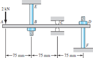
The steel beam ABCD shown is simply supported at C as shown and supported at B and D by shoulder steel bolts, each having a diameter of 8 mm. The lengths of BE and DF are 50 mm and 65 mm, respectively. The beam has a second area moment of 21(103) mm4. Prior to loading, the members are stress-free. A force of 2 kN is then applied at point A. Using procedure 2 of Sec. 4–10, determine the stresses in the bolts and the deflections of points A, B, and D.
Problem 4–102
The stresses in the bolts.
The deflection at point A.
The deflection at point B.
The deflection at point D.
Answer to Problem 102P
The stress in the bolt
The deflection at point A is
The deflection at point B is
The deflection at point D is
Explanation of Solution
The Figure (1) shows the free body diagram of the steel beam ABCD.
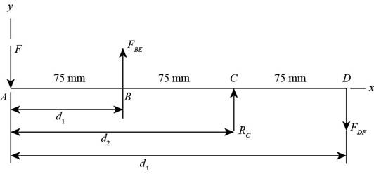
Figure (1)
Here, the applied load at point
Refer to procedure 2 from Sec. 4–10.
Write the expression for the net force in the beam
Write the expression for the net moment about point
Here, the length of the beam is
The Figure (2) shows the beam at section (1).
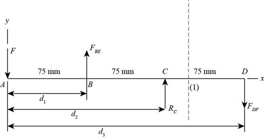
Figure (2)
Write the expression for the bending moment at section (1).
Here, the bending moment at section (1) is
Write the expression for the bending moment in terms of elastic equation.
Here, the modulus of elasticity is
Substitute
Integrate the above expression.
Further integrate the above expression.
Write the expression for the area of the bolt.
Here, the area of the bolt is
Write the expression for elongationin the steel boltat point B.
Here, the elongation is
Write the expression for elongation in the steel bolt at point D
Here, the elongation is
Applying Boundary conditions.
At
Substitute
At
Substitute
At
Substitute
Write the expression for the normal stress in section BE.
Here, the normal stress is
Write the expression for the normal stress in section DF.
Here, the normal stress is
Conclusion:
Refer to Table A-5 “Physical Constants of Materials”, obtain the properties of modulus of elasticity for steel as
Substitute
Substitute
Substitute
Substitute
Write Equation (I), Equation (II), Equation (XIV), Equation (XV), and Equation (XVI) in matrix form.
Solve the above matrix Equation to obtain reactions as follows.
Solve the above matrix to obtain the constants.
Substitute
Thus, the stress in the bolt
Substitute
Thus, the stress in the bolt
Calculate deflection at point
Substitute
Thus, the deflection at point
Calculate deflection at point
Substitute
Thus, the deflection at point
Calculate deflection at point
Substitute
Thus, the deflection at point
Want to see more full solutions like this?
Chapter 4 Solutions
Shigley's Mechanical Engineering Design (McGraw-Hill Series in Mechanical Engineering)


- Two steel tubes are joined at B by four pins (dp= 11 mm), as shown in the cross section a—a in the fiaure. The outer diameters of the tubes are dAB= 41 mm and dBC= 28 mm. The wall thickness are tAB= 6.5 mm and tBC= 7.5 mm. The yield stress in tension for the steel is sy = 200 MPa and the ultimate stress in tension is ??U:= 340 MPa. The corresponding yield and ultimate values in shear for the pm are 80 MPa and 140 MPa, respectively. Finally, the yield and ultimate values in bearing R between the pins and the tubes are 260 MPa, and 450 MPa, respectively. Assume that the factors safety with respect to yield stress and ultimate stress are 3.5 and 4.5. respectively. (a) Calculate the allowable tensile force P allowconsidering tension in the tube (b) Recompute P allowfor shear in the pins.(c)Finaly, recomputed Pallowfor bearing between the pm and the tubes. Which is the tubes. Which is the controlling value value of P?arrow_forwardA sign for an automobile service station is supported by two aluminum poles of hollow circular cross section, as shown in the figure. The poles are being designed to resist a wind pressure of 75 lb/ft" against the full area of the sign. The dimensions of the poles and sign are hx= 20 ft, /r =5 ft, and h = 10 ft. To prevent buckling of the walls of the poles, the thickness e is specified as one-tenth the outside diameter d. (a) Determine the minimum required diameter of the poles based upon an allowable bending stress of 7500 psi in the aluminum. (b) Determine the minimum required diameter based upon an allowable shear stress of 300 psi.arrow_forwardTwo pipe columns (AB, FC) are pin-connected to a rigid beam (BCD), as shown in the figure. Each pipe column has a modulus of E, but heights (L1or L2) and outer diameters (d1or different for each column. Assume the inner diameter of each column is 3/4 of outer diameter. Uniformly distributed downward load q = 2PIL is applied over a distance of 3L/4 along BC, and concentrated load PIA is applied downward at D. (a) Derive a formula for the displacementarrow_forward
- A long slender column ABC is pinned at ends A and C and compressed by an axial force F (sec figure). At the midpoint B, lateral support is provided to prevent deflection in the plane of the figure. The column is a steel wide-flange section (W 250 × 67) with E = 200 GPa. The distance between lateral supports is L = 5.5 m. Calculate the allowable load P using a factor of safety n = 2.4, taking into account the possibility of Eu 1er buckling about cither principal centroidal axis (i.e., axis 1-1 or axis 2-2).arrow_forwardRepeat Problem 11.2-3 assuming that R= 10 kN · m/rad and L = 2 m.arrow_forwardRepeat Problem 11.3-9. Use two C 150 × 12.2 steel shapes and assume that E = 205 GPa and L = 6 m.arrow_forward
- The cross section of a narrow-gage railway bridge is shown in part a of the figure. The bridge is constructed with longitudinal steel grinders that support the wood cross ties. The bridge is constructed with longitudinal steel girders that support the wood cross ties. The girders are restrained against lateral buckling by diagonal bracing, as indicated by the dashed lines. The spacing of the girders is S1= 50 in. and the spacing of the rails is s2= 30 in. The load transmitted by each rail to a single tie is P = 1500 1b. The cross section of a tie, shown in part b of the figure, has a width b =5.0 in. and depth d. Determine the minimum value of d based upon an allowable bending stress of 1125 psi in the wood tie. (Disregard the weight of the tie itself.)arrow_forwardA wood beam AB with a rectangular cross section (4 in. × 6 in.) serving as a roof purlin is simply supported by the top chords of two adjacent roof trusses. The beam is subjected to distributed load q acting in the vertical direction through the centroid of the purlin cross section. The top chords of the trusses have a slope of = 27°. The purlin has length L =75 in. Determine the permissible distributed load q based on the allowable compressive and tensile stress in the beam eall = 2 ksi.arrow_forwardSolve Problem 11.3-3 for a W 10 × 45 steel column having a length L = 28 ft.arrow_forward
- A tie-down on the deck of a sailboat consists of a bent bar boiled at both ends, as shown in the figure. The diameter dBof the bar is 1/4 in., the diameter D Wof the washers is 7/8 in., and the thickness is of the fiberglass deck is 3/8 in. If the allowable shear stress in the fiberglass is 300 psi, and the allowable bearing pressure between the washer and the fiberglass is 550 psi, what is the allowable load P allowon the tie-down?arrow_forwardA wood beam AB on simple supports with span length equal to 10 ft is subjected to a uniform load of intensity 125 lb/ft acting along the entire length of the beam, a concentrated load of magnitude 7500 lb acting at a point 3 ft from the right-hand support, and a moment at A of 18,500 ft-lb (sec figure). The allowable stresses in bending and shear, respectively, are 2250 psi and 160 psi. From the table in Appendix G, select the lightest beam that will support the loads (disregard the weight of the beam). Taking into account the weight of the beam (weight density = 35 lb/ft3), verify that the selected beam is satisfactory, or if it is not, select a new beam.arrow_forwardA bracket ABCD having a hollow circular cross section consists of a vertical arm AB{L = 6 ft), a horizontal arm BC parallel to the v0 axis, and a horizontal arm CD parallel to the -0 axis (see figure). The arms BC and CD have lengths b}= 3.6 ft and b2= 2,2 ft, respectively. The outer and inner diameters of the bracket are d-, = 7,5 in. and dx= 6,8 in. An inclined load P = 2200 lb acts at point D along line DH. Determine the maximum tensile, compressive, and shear stresses in the vertical armarrow_forward
 Mechanics of Materials (MindTap Course List)Mechanical EngineeringISBN:9781337093347Author:Barry J. Goodno, James M. GerePublisher:Cengage Learning