
Concept explainers
Videos
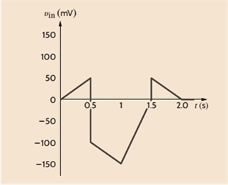
An amplifier has a gain of 15 and the input waveform shown in Fig. P4.1. Draw the output waveform.
To draw:
The output waveform using input waveform and gain of the amplifier.
Explanation of Solution
Given:
Amplifier has a gain of 15 and input waveform shown below.
Calculation:
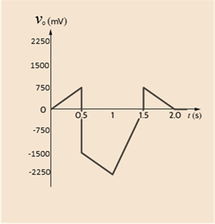
For an amplifier, output voltage is product of gain and its input voltage.
In the given figure, calculate the output voltage by the above formulae at different time to form a graph.
At
At
At
At
At
The output waveform for the given input is shown below.
Want to see more full solutions like this?
Chapter 4 Solutions
Basic Engineering Circuit Analysis


- P4ohm using SPT and Thevenin's Theoremarrow_forwardReferenced instrumentation amplifier The diagram above represents a 2-amp instrumentation amplifier with a reference input (Vref). The equation that best defines the relationship between the inputs and outputs of the circuit is:arrow_forwardWhat would be the Q-point currents in M4 and M5 in the amplifier as shown if VDD = VSS = 16 V, I2 = 250 μA, RG = 7 kΩ, RL = 2 kΩ, and VT N = 0.75 V, VT P = −0.75 V, Kn = 5 mA/V2, and Kp = 2 mA/V2?arrow_forward
- Determine the differential equation that define the loop connected to the voltage source.arrow_forwardThe figure below shows an inverting amplifier connected to a load RL. Determine the power gain of the amplifier. power gain for the amplifier, G, is defined as the power ratio that reaches the load RL versus the power supplied by the source VS.arrow_forwardAn amplifier is required with a voltage gain of 1000 and will be designed using a cascade of several C-S amplifier stages operating from a single 12-V power supply. Estimate the minimum number of amplifier stages required to achieve this gain.arrow_forward
- (a) Find the Q-point for the transistor in the circuit in Fig. P4.114(a) if V DD =+12 V. (b) Repeat for the circuit in Fig. 4.114(b)arrow_forwardFor the circuit shown in Fig. P4.1 , (a) Write and verify a gate-level HDL model of the circuit.2. (b) Compare your results with those obtained for Problem 4.1 .arrow_forwardFor the circuit shown above, find an expression between the inputs, v1, v2, v3 and v4 and vO. Make simplifying assumptions about the OP-AMP such as v+=v- but you must state the conditions for which this assumption is correct. As soon as possible!arrow_forward
- Find the value of R1 required so that the amp has gain, G= -8.24 given R2=560kΩarrow_forwardA C-S amplifier is operating from a single 9-V supply. What is the maximum value of VGS −VT N that can be used if the amplifier must have a gain of atleast 25?arrow_forwarddetermine the P4ohm by using (a) Super position Theorem (SPT) and (b) Thevenin's Theoremarrow_forward
 Introductory Circuit Analysis (13th Edition)Electrical EngineeringISBN:9780133923605Author:Robert L. BoylestadPublisher:PEARSON
 Delmar's Standard Textbook Of ElectricityElectrical EngineeringISBN:9781337900348Author:Stephen L. HermanPublisher:Cengage Learning
 Programmable Logic ControllersElectrical EngineeringISBN:9780073373843Author:Frank D. PetruzellaPublisher:McGraw-Hill Education
 Fundamentals of Electric CircuitsElectrical EngineeringISBN:9780078028229Author:Charles K Alexander, Matthew SadikuPublisher:McGraw-Hill Education
 Electric Circuits. (11th Edition)Electrical EngineeringISBN:9780134746968Author:James W. Nilsson, Susan RiedelPublisher:PEARSON
 Engineering ElectromagneticsElectrical EngineeringISBN:9780078028151Author:Hayt, William H. (william Hart), Jr, BUCK, John A.Publisher:Mcgraw-hill Education,