
Videos
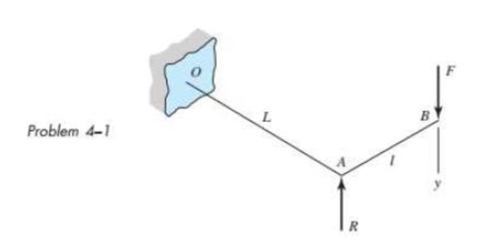
The figure shows a torsion bar OA fixed at O, simply supported at A, and connected to a cantilever AB. The spring rate of the torsion bar is kT, in newton-meters per radian, and that of the cantilever is kl, in newtons per meter. What is the overall spring rate based on the deflection y at point B?
The overall spring rate based on the deflection
Answer to Problem 1P
The overall spring rate based on the deflection
Explanation of Solution
Write the expression for the stiffness of the torsion bar.
Here, the torsional stiffness of the bar is
Write the expression of the torque on the torsional bar.
Here, the length of the bat is
Since the force
Substitute
Write the expression for stiffness of the cantilever portion AB.
Here, the lateral stiffness of the bar is
Write the expression for net deflection of a combined system.
Here, total deflection is
The net defection of the combined system is the combination of the torsional deflection and lateral deflection.
Write the equation of net deflection of the combined system.
Conclusion:
Substitute the value of
Substitute
Thus, the overall spring rate based on the deflection
Want to see more full solutions like this?
Chapter 4 Solutions
SHIGLEY'S MECH.ENGIN....(LOOSE)>CUSTOM<


- A bumping post at the end of a track in a railway yard has a spring constant k = 8.0 MN/m (see figure). The maximum possible displacement d or the end of the striking plate is 450 mm. What is the maximum velocity vmaxthat a railway car of weight W = 545 kN can have without damaging the bumping post when it strikes it?arrow_forwardA bumper for a mine car is constructed with a spring of stiffness k = 1120 lb/in. (see figure). If a car weighing 3450 lb is traveling at velocity v = 7 mph when it strikes the spring, what is the maximum shortening of the spring?arrow_forwardA cantilever beam model is often used to represent micro-clectrical-mechanical systems (MEMS) (sec figure}. The cantilever beam is made of polysilicon (E = 150 GPa) and is subjected to an electrostatic moment M applied at the end of the cantilever beam. 1 f dimensions arc h — 2 [im, h — 4 ^m, and L = 520 ^mt find expressions for the tip deflection and rotation of the cantilever beam in terms of moment M.arrow_forward
- A cantilever beam of a length L and loaded by a uniform load of intensity q has a fixed support at A and spring support at B with rotational stiffness kR. A rotation B at B results in a reaction moment MB=kRxB. Find rotation B and displacement Bat end B. Use the second-order differential equation of the deflection curve to solve for displacements at end B.arrow_forwardRepeat Problem 2.3-18, but assume that the bar is made of copper alloy. Calculate the displacements SBand Scif P = 50 kips, L = 5 ft = 3/5 in., b1= 2.75 in., b2= 3 in., and E = 16,000 ksi.arrow_forward-4-4 A cantilever beam is supported at B by cable BC. The beam carries a uniform load q = 200 N/M. If the length of the beam is L = 3 m, find the force in the cable and the reactions at A. Ignore the axial flexibility of the cable.arrow_forward
- A seesaw weighing 3 lb/ft of length is occupied by two children, each weighing 90 lb (see figure). The center of gravity of each child is 8 ft from the fulcrum. The board is 19 ft long, 8 in. wide, and 1.5 in. thick. What is the maximum bending stress in the board?arrow_forwardTwo pipe columns (AB, FC) are pin-connected to a rigid beam (BCD), as shown in the figure. Each pipe column has a modulus of E, but heights (L1or L2) and outer diameters (d1or different for each column. Assume the inner diameter of each column is 3/4 of outer diameter. Uniformly distributed downward load q = 2PIL is applied over a distance of 3L/4 along BC, and concentrated load PIA is applied downward at D. (a) Derive a formula for the displacementarrow_forwardRepeat Problem 2.3-4, but now include the weight of the bar. Sec Table 1.1 in Appendix I for the weight density of steel.arrow_forward
- Two rigid bars are connected to each other by two linearly elastic springs. Before loads are applied, the lengths or the springs are such, that the bars are parallel and the springs are without stress. (a) Derive a formula for the displacement E4at point 4 when the load P is applied at joint 3 and moment PL is applied at joint 1. as shown in the figure part a. (Assume that the bars rotate through very small angles under the action of load P.) (b) Repeat part (a) if a rotational spring, kr= kL2, is now added at joint 6. What is the ratio of the deflection d4 in the figure part a to that in the figure part b ?arrow_forwardAround brass bar of a diameter d1= 20mm has upset ends each with a diameter d2= 26 mm (see figure). The lengths of the segments of the bar are L1= 0.3 m and L2= 0.1 m. Quarter-circular fillets are used at the shoulders of the bar, and the modulus of elasticity of the brass is E = 100 GPa. If the bar lengthens by 0.12 mm under a tensile load P, what is the maximum stress ??maxin the bar?arrow_forwardA thin steel beam AB used in conjunction with an electromagnet in a high-energy physics experiment is securely bolted to rigid supports (see figure), A magnetic field produced by coils C results in a force acting on the beam. The force is trapezoidally distributed with maximum intensity q0= 18 kN/m. The length of the beam between supports is L = 200 mm, and the dimension c of the trapezoidal load is 50 mm. The beam has a rectangular cross section with width b = 60 and height h = 20 mm. Determine the maximum bending stress max and the maximum deflection for the beam. (Disregard any effects of axial deformations and consider only the effects of bending. Use E = 200 GPa.)arrow_forward
 Mechanics of Materials (MindTap Course List)Mechanical EngineeringISBN:9781337093347Author:Barry J. Goodno, James M. GerePublisher:Cengage Learning