
Concept explainers
Videos
Find the power dissipated by each resistor in the circuit.
Answer to Problem 36E
The power dissipated by
Explanation of Solution
Calculation:
The circuit diagram is redrawn as shown in Figure 1.
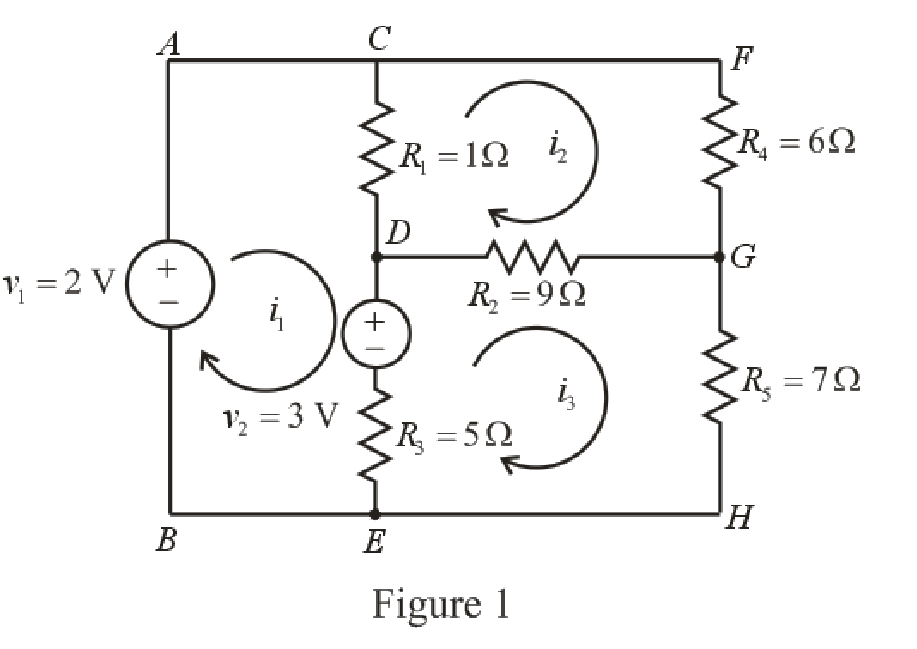
Refer to the redrawn Figure 1
Apply KVL in the mesh
Here,
Apply KVL in the mesh
Here,
Apply KVL in the mesh
Here,
The expression for the power dissipated by the resistor is as follows.
Here,
The current flowing through the
Here,
The current flowing through the
Here,
The current flowing through the
Here,
Refer to the redrawn Figure 1.
Substitute
Substitute
Substitute
Rearrange the equation (8), (9) and (10).
The equations so formed can be written in matrix form as,
Therefore, by Cramer’s rule,
The determinant of coefficient matrix is as follows,
The 1st determinant is as follows.
The 2nd determinant is as follows.
The 3rd determinant is as follows.
Simplify for
Simplify for
Simplify for
Substitute
Substitute
Substitute
Substitute
Substitute
Substitute
Substitute
Substitute
Conclusion:
Thus, the power dissipated by
Want to see more full solutions like this?
Chapter 4 Solutions
Loose Leaf for Engineering Circuit Analysis Format: Loose-leaf


- Given the circuit in Fig. 4.117, obtain the Norton equivalent as viewed from terminals:arrow_forwardA black box with a circuit in it is connected to a variable resistor. An ideal ammeter (with zero resistance) and an ideal voltmeter (with infinite resistance) are used to measure current and voltage as shown in Fig. 4.143.arrow_forwardQuestion: 4.12 Determine vo in the circuit of Fig. 4.80 using the superposition principle.arrow_forward
- #7. Use Nodal analysis, Mesh Analysis, and Superposition to solve following problem: Determine v, in the circuit of Fig. 4.80]arrow_forward2. Is the total power dissipated in resistance R of Fig. (4-7), is equal to the sum of the powers due to each of the sources Vand ,acting alone? Explain.arrow_forwardUse superposition to find v0 in the circuit of Fig.4.77.arrow_forward
- 4.48 Determine the Norton equivalent at terminals a-b forthe circuit in Fig. 4.115.arrow_forward4.For the circuit shown in fig.4. Using superposition theorem, find the current through the resistor I.arrow_forwardUsing the superstition theorem, how would I prove the second images problem, given that #2 (voltage source was replaced with a short) measured 5 amps, and #4 (had the current source replaced with an open circuit) measured 1.6 amps?arrow_forward
 Introductory Circuit Analysis (13th Edition)Electrical EngineeringISBN:9780133923605Author:Robert L. BoylestadPublisher:PEARSON
 Delmar's Standard Textbook Of ElectricityElectrical EngineeringISBN:9781337900348Author:Stephen L. HermanPublisher:Cengage Learning
 Programmable Logic ControllersElectrical EngineeringISBN:9780073373843Author:Frank D. PetruzellaPublisher:McGraw-Hill Education
 Fundamentals of Electric CircuitsElectrical EngineeringISBN:9780078028229Author:Charles K Alexander, Matthew SadikuPublisher:McGraw-Hill Education
 Electric Circuits. (11th Edition)Electrical EngineeringISBN:9780134746968Author:James W. Nilsson, Susan RiedelPublisher:PEARSON
 Engineering ElectromagneticsElectrical EngineeringISBN:9780078028151Author:Hayt, William H. (william Hart), Jr, BUCK, John A.Publisher:Mcgraw-hill Education,