
The current
Answer to Problem 4.10HP
The expression for the current through the inductor for different time interval is
Explanation of Solution
Calculation:
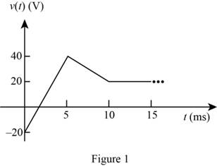
The given diagram is shown in Figure 1
The conversion from
The conversion from
The conversion from
The conversion from
The conversion from
The conversion from
The conversion from
The conversion from
From the graph the expression for the voltage between the points
From the graph the expression for the voltage between the points
From the graph the expression for the voltage at
The expression for the voltage across the inductor is given by,
The expression for the current through the inductor is given by,
Substitute
Substitute
Substitute
Substitute
Substitute
Substitute
Substitute
Substitute
The expression for the current through the inductor is given by,
Conclusion:
Therefore, the expression for the current through the inductor for different time interval is
Want to see more full solutions like this?
Chapter 4 Solutions
Principles and Applications of Electrical Engineering

- Use the defining law for a capacitor to find the current iC(t) corresponding to the voltage shown in Figure P4.27. Sketch your result.arrow_forwardIf the plots shown in Figure P4.19 are the voltageacross and the current through an ideal inductor,determine the inductance.arrow_forwardIn Figure P4.64, let R=500 Ω. Using the inductor current, derive the Characteristic Equation.arrow_forward
- Consider the circuit of Figure P4.17, in which the switch instantaneously moves back and forth between contacts A and B, spending 2 seconds in each position. Thus, the capacitor repeatedly charges for 2 seconds and then discharges for 2 seconds. Assume that v C ( 0 )=0 and that the switch moves to position A at t=0. Determine v C ( 2 ), v C ( 4 ), v C ( 6 ), and v C ( 8 ).arrow_forwardThe voltage across and the current through acapacitor are shown in Figure P4.20. Determine thevalue of the capacitance.arrow_forwardIf the waveform shown in Figure P4.15 is thevoltage across a capacitor plotted as a function of timewithvPK = 20V, T = 40 μs, C = 680nFdetermine and plot the waveform for the currentthrough the capacitor as a function of time.arrow_forward
- The initial voltage across the capacitor shown in Figure P4.3 is v C ( 0+ )=−10 V. Find anexpression for the voltage across the capacitor as a function of time. Also, determine the time t0at which the voltage crosses zero.arrow_forwardThe voltage waveform shown in Figure P4.24appears across a 100-mH inductor and a 500-μFcapacitor. Plot the capacitor and inductor currents,iC(t) and iL(t), assuming iL(0) = 0A.arrow_forwardWe know that the capacitor shown in Figure P4.11 is charged to a voltage of 10 V priorto t=0.a. Find expressions for the voltage across the capacitor vC(t) and the voltage across theresistor vR(t) for all time.b. Find an expression for the power delivered to the resistor.c. Integrate the power from t=0 to t=∞ to find the energy delivered.d. Show that the energy delivered to the resistor is equal to the energy stored in thecapacitor prior to t=0.arrow_forward
- The initial voltage across the capacitor shown in Figure P4.3 is v C ( 0+ )=0. Find an expression for the voltage across the capacitor as a function of time, and sketch to scale versus timearrow_forwardThe current waveform shown in Figure P4.23 flowsthrough a 2-H inductor. Plot the inductor voltage vL(t).arrow_forwardDetermine expressions for and sketch v R ( t ) to scale versus time for the circuit of Figure P4.43. The circuit is operating in steady state with the switch closed prior to t=0. Consider the time interval −1≤t≤5 ms.arrow_forward
 Introductory Circuit Analysis (13th Edition)Electrical EngineeringISBN:9780133923605Author:Robert L. BoylestadPublisher:PEARSON
 Delmar's Standard Textbook Of ElectricityElectrical EngineeringISBN:9781337900348Author:Stephen L. HermanPublisher:Cengage Learning
 Programmable Logic ControllersElectrical EngineeringISBN:9780073373843Author:Frank D. PetruzellaPublisher:McGraw-Hill Education
 Fundamentals of Electric CircuitsElectrical EngineeringISBN:9780078028229Author:Charles K Alexander, Matthew SadikuPublisher:McGraw-Hill Education
 Electric Circuits. (11th Edition)Electrical EngineeringISBN:9780134746968Author:James W. Nilsson, Susan RiedelPublisher:PEARSON
 Engineering ElectromagneticsElectrical EngineeringISBN:9780078028151Author:Hayt, William H. (william Hart), Jr, BUCK, John A.Publisher:Mcgraw-hill Education,