
Suppose we have a capacitance C discharging through a resistance R. Define and give an expression for the time constant. To attain a long time constant, do we need large or small values for R? For C?
The expression for the time constant of the discharging RC circuit and the magnitude of values of R and C for the condition of a large time constant.
Answer to Problem 4.1P
The expression for the time constant for the discharging RC circuit is given as
The value of the values of R and C must be high for a large time constant.
Explanation of Solution
Given information:
Initially, the capacitor is fully charged, the charge on the plates of the capacitor at
The capacitance of the capacitor is C, the resistance of the resistor is R and the time constant of the circuit is
Calculation:
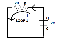
The circuit diagram of the discharging RC circuit is shown below. The capacitor is initially fully charged. Since it is a discharging circuit, the charges on the plate of the capacitor are Q after a time
Applying K.V.L in loop 1
Let the charge on the capacitor at any instant is
Solving the differential equation (2) using the variable separable method,
Where
Hence, the time constant is proportional to the values of resistance and capacitance in the circuit.
To attain a large time constant large value of R is needed as R is directly proportional to the time constant. Also, a large value of C is needed for a large time constant.
Want to see more full solutions like this?
Chapter 4 Solutions
Mastering Engineering with Pearson eText -- Standalone Access Card -- for Electrical Engineering: Principles & Applications
Additional Engineering Textbook Solutions
Fundamentals of Applied Electromagnetics (7th Edition)
Introductory Circuit Analysis (13th Edition)
Starting out with Visual C# (4th Edition)
Engineering Mechanics: Statics & Dynamics (14th Edition)
Web Development and Design Foundations with HTML5 (8th Edition)
Artificial Intelligence: A Modern Approach

- Give the expression for the time constant of a circuit consisting of an inductance with an initial current in series with a resistance R. To attain a long time constant, do we need large or small values for R? For L?arrow_forwardState the phase relationship between current and voltage for a resistance, for an inductance, and for a capacitance.arrow_forwardwrite the differences between capacitors connected in series and parallel. At Voltage, How it looks, current, Capacitor, featuresarrow_forward
- When we talk about capacitance of capacitor we normally say that capacitance depends on the size, shape, and position of the two capacitors and dielectric constant K. What then did we mean when we say that capacitance is constant in the equation Q = CV?arrow_forwardDraw schematics to illustrate why the capacitance is formed in DoubleLayer (DL) in Electrostatic Double-Layer Capacitor (EDLC). State thecapacitance’s difference between Double Layer (DL) and conventional capacitors?arrow_forwardIn the first method to write the equation, why is the capacitor value not included in the equation at first?arrow_forward
- What is the net, coupling capacitance cm and lateral capacitance? Explain this circuit in a really basic wayarrow_forwardderive equation for induced emfs across the two inductors given in the figure 2?arrow_forwardHow does the product rule of differentiation (differential calculus) useful in Capacitance and Capacitors in Series and Parallel Connections?arrow_forward
- Define the continuity equation, then discuss the relaxation time in dielectric and conducting materials.arrow_forwardWhat are the steps in solving a circuit having a resistance, a source, and an inductance (or capacitance)?arrow_forwardWhat is the practical application of a circuit that you can tune such that it reaches some minimum resistance? Would there be an application to being able to tune where that minimum occurs, by changing the capacitance or inductance of the circuit?arrow_forward
 Introductory Circuit Analysis (13th Edition)Electrical EngineeringISBN:9780133923605Author:Robert L. BoylestadPublisher:PEARSON
 Delmar's Standard Textbook Of ElectricityElectrical EngineeringISBN:9781337900348Author:Stephen L. HermanPublisher:Cengage Learning
 Programmable Logic ControllersElectrical EngineeringISBN:9780073373843Author:Frank D. PetruzellaPublisher:McGraw-Hill Education
 Fundamentals of Electric CircuitsElectrical EngineeringISBN:9780078028229Author:Charles K Alexander, Matthew SadikuPublisher:McGraw-Hill Education
 Electric Circuits. (11th Edition)Electrical EngineeringISBN:9780134746968Author:James W. Nilsson, Susan RiedelPublisher:PEARSON
 Engineering ElectromagneticsElectrical EngineeringISBN:9780078028151Author:Hayt, William H. (william Hart), Jr, BUCK, John A.Publisher:Mcgraw-hill Education,