
Mechanics of Materials (MindTap Course List)
9th Edition
ISBN: 9781337093347
Author: Barry J. Goodno, James M. Gere
Publisher: Cengage Learning
expand_more
expand_more
format_list_bulleted
Videos
Textbook Question
Chapter 4, Problem 4.3.17P
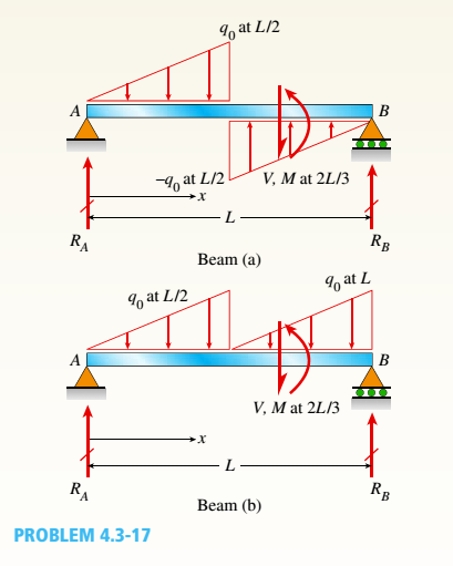
Find expressions for shear force V and moment Mat x = 2L/3 of beam (a) in terms of peak load intensity q0 and beam length variable L. Repeat for beam (b).
Expert Solution & Answer

Trending nowThis is a popular solution!

Students have asked these similar questions
An I-beam has a flange width b = 400 mm , height hℎ = 400 mm , web thickness tw = 13 mm , and flange thickness tf = 21 mm . Use the following steps to calculate the shear flow at the point shown, where x = 55 mm .
A) The formula for the shear flow includes the moment of inertia of the whole cross section, I, about the neutral axis. Calculate the moment of inertia.
B) The shear flow at the point depends on the value of Q for the portion of the upper flange to the right of the point. Calculate the value of Q
C) Use the results from Parts A and B to calculate the shear flow at the point in the upper flange 55 mm to the right of the web if the shear force on the section is V = 4.6 kN
A beam segment subjected to internal bending moments at sections A and B is shown along with a sketch of the cross-sectional dimensions. The beam segment is subjected to internal bending moments of MA = 1390 N·m and MB = 3080 N·m. The segment length is Δx = 180 mm. Consider area (2) and use cross-sectional dimensions of b = 92 mm, d = 240 mm, and d2 = 68 mm. (a) sketch a side view of the beam segment and plot the distribution of bending stresses acting at sections A and B. Indicate the magnitudes of key bending stresses on the sketch, including the stresses at the top and bottom of area (2) on both sections A and B. Tensile stresses are positive, while compressive stresses are negative. (b) determine the resultant forces acting in the x direction on the specified area at sections A and B, and show these resultant forces on the sketch. Tensile forces are positive, while compressive forces are negative. (c) determine the magnitude of the horizontal force required to satisfy equilibrium…
An I-beam has a flange width b = 400 mm , height h = 400 mm , web thickness tw = 13 mm , and flange thickness tf = 21 mm . Use the following steps to calculate the shear flow at the point shown, where x = 55 mm .
A) The formula for the shear flow includes the moment of inertia of the whole cross section, I, about the neutral axis. Calculate the moment of inertia.
B) The shear flow at the point depends on the value of Q for the portion of the upper flange to the right of the point. Calculate the value of Q
C) Use the results from Parts A and B to calculate the shear flow at the point in the upper flange 55 mm to the right of the web if the shear force on the section is V = 4.6 kN
Chapter 4 Solutions
Mechanics of Materials (MindTap Course List)
Ch. 4 - Calculate the shear force V and bending moment...Ch. 4 - Determine the shear force V and bending moment M...Ch. 4 - Determine the shear force V and bending moment M...Ch. 4 - Calculate the shear force V and bending moment M...Ch. 4 - Consider the beam with an overhang shown in the...Ch. 4 - The beam ABC shown in the figure is simply...Ch. 4 - The beam ABCD shown in the figure has overhangs at...Ch. 4 - At a full d raw, an archer applies a pull of 130 N...Ch. 4 - A curved bar ABC is subjected to loads in the form...Ch. 4 - Under cruising conditions, the distributed load...
Ch. 4 - A beam ABCD with a vertical arm CE is supported as...Ch. 4 - A simply supported beam AB supports a trapezoid...Ch. 4 - Beam ABCD represents a reinforced-concrete...Ch. 4 - Find shear (V) and moment (M) at x = 3L/4 for the...Ch. 4 - Find expressions for shear force V and moment M at...Ch. 4 - Find expressions for shear force V and moment Mat...Ch. 4 - Find expressions for shear force V and moment Mat...Ch. 4 - Find expressions for shear force V and moment M at...Ch. 4 - Find expressions for shear force V and moment M at...Ch. 4 - Find expressions for shear force V and moment M at...Ch. 4 - A cable with force P is attached to a frame at A...Ch. 4 - Find expressions for shear force V and moment M at...Ch. 4 - A cable with force P is attached to a frame at D...Ch. 4 - Frame ABCD carries two concentrated loads (2P at T...Ch. 4 - Frame ABC has a moment release just left of joint...Ch. 4 - The simply supported beam ABCD is loaded by a...Ch. 4 - The centrifuge shown in the figure rotates in a...Ch. 4 - Draw the shear-Force and bending-moment diagrams...Ch. 4 - A simple beam AB is subjected to a counter...Ch. 4 - Draw the shear-force and bending-moment diagrams...Ch. 4 - The cantilever beam AB shown in the figure is...Ch. 4 - Cantilever beam AB carries an upward uniform load...Ch. 4 - The simple beam AB shown in the figure is...Ch. 4 - A simple beam AB subjected to couples M1and 3M2...Ch. 4 - A simply supported beam ABC is loaded by a...Ch. 4 - A simply supported beam ABC is loaded at the end...Ch. 4 - A beam ABC is simply supported at A and B and has...Ch. 4 - Beam ABCD is simply supported at B and C and has...Ch. 4 - Draw the shear-force and bending-moment diagrams...Ch. 4 - The simple beam AB supports a triangular load of...Ch. 4 - The beam AB shown in the figure supports a uniform...Ch. 4 - A cantilever beam AB supports a couple and a...Ch. 4 - The cantilever beam A B shown in the figure is...Ch. 4 - Beam ABC has simple supports at .A and B. an...Ch. 4 - Beam ABC with an overhang at one end supports a...Ch. 4 - Consider the two beams shown in the figures. Which...Ch. 4 - The three beams in the figure have the same...Ch. 4 - The beam ABC shown in the figure is simply...Ch. 4 - A simple beam AB is loaded by two segments of...Ch. 4 - Two beams (see figure) are loaded the same and...Ch. 4 - The beam A BCD shown in the figure has overhangs...Ch. 4 - A beam ABCD with a vertical arm CE is supported as...Ch. 4 - Beams ABC and CD are supported at A,C, and D and...Ch. 4 - The simple beam ACE shown in the figure is...Ch. 4 - A beam with simple supports is subjected to a...Ch. 4 - A beam of length L is designed to support a...Ch. 4 - The compound beam ABCDE shown in the figure...Ch. 4 - Draw the shear-force and bending-moment diagrams...Ch. 4 - The shear-force diagram for a simple beam is shown...Ch. 4 - The shear-force diagram for a beam is shown in the...Ch. 4 - A compound beam (see figure) has an internal...Ch. 4 - A compound beam (see figure) has an shear release...Ch. 4 - A simple beam AB supports two connected wheel...Ch. 4 - The inclined beam represents a ladder with the...Ch. 4 - Beam ABC is supported by a tie rod CD as shown....Ch. 4 - A plane frame (see figure) consists of column AB...Ch. 4 - The plane frame shown in the figure is part of an...
Knowledge Booster


Learn more about
Need a deep-dive on the concept behind this application? Look no further. Learn more about this topic, mechanical-engineering and related others by exploring similar questions and additional content below.Similar questions
- A fixed-end beam AB of a length L is subjected to a uniform load of intensity q acting over the middle region of the beam (sec figure). Obtain a formula for the fixed-end moments MAand MBin terms of the load q, the length L, and the length h of the loaded part of the beam. Plot a graph of the fixed-end moment MAversus the length b of the loaded part of the beam. For convenience, plot the graph in the following nondimensional form: MAqL2/l2versusbL with the ratio b/L varying between its extreme values of 0 and 1. (c) For the special case in which ù = h = L/3, draw the shear-force and bending-moment diagrams for the beam, labeling all critical ordinates.arrow_forwardFind expressions for shear force V and moment M at mid-span of beam AB in terms of peak load intensity q0and beam length variables a and L Let a = 5L/b.arrow_forwardThe hollow box beam shown in the figure is subjected to a bending moment M of such magnitude that the flanges yield but the webs remain linearly elastic. (a) Calculate the magnitude of the moment M if the dimensions of the cross section are A = 15 in., A] = 12.75 in., h = 9 in., and ey =7.5 in. Also, the yield stress is eY = 33 ksi. (b) What percent of the moment M is produced by the elastic core?arrow_forward
- Find expressions for shear force V and moment Mat x = 2L/3 of beam (a) in terms of peak load intensity q0and beam length variable L. Repeat for beam (b) but at x = L/2.arrow_forward.2 A ligmio.irc ii supported by two vorlical beams consistins: of thin-walled, tapered circular lubes (see ligure part at. for purposes of this analysis, each beam may be represented as a cantilever AB of length L = 8.0 m subjected to a lateral load P = 2.4 kN at the free end. The tubes have a constant thickness ; = 10.0 mm and average diameters dA = 90 mm and dB = 270 mm at ends A and B, re s pec lively. Because the thickness is small compared to the diameters, the moment of inerlia at any cross section may be obtained from the formula / = jrrf3;/8 (see Case 22, Appendix E); therefore, the section modulus mav be obtained from the formula S = trdhlA. (a) At what dislance A from the free end docs the maximum bending stress occur? What is the magnitude trllul of the maximum bending stress? What is the ratio of the maximum stress to the largest stress (b) Repeat part (a) if concentrated load P is applied upward at A and downward uniform load q {-x) = 2PIL is applied over the entire beam as shown in the figure part b What is the ratio of the maximum stress to the stress at the location of maximum moment?arrow_forwardA simple beam AB of length L is subjected to loads that produce a symmetric deflection curve with maximum deflection S at the midpoint of the span (see figure). How much strain energy U is stored in the beam if the deflection curve is (a) a parabola and (b) a half wave of a sine curve?arrow_forward
- Cantilever beam AB carries an upward uniform load of intensity q1from x = 0 to L/2 (see Fig. a) and a downward uniform load of intensity q from x = L/2 to L. Find q1in terms of q if the resulting moment at A is zero. Draw V and M diagrams for the case of both q and qtas applied loadings. Repeat part (a) for the case of an upward triangularly distributed load with peak intensity q0(see Fig. b). For part (b), find q0, instead of q1arrow_forwardA cantilever beam AB of length L = 6.5 ft supports a trapezoidal distributed load of peak intensity 4, and minimum intensity q/2tthat includes the weight of the beam (see figure). The beam is a steel W 12 × 14 wide-flange shape (see Table F-l(a), Appendix F). Calculate the maximum permissible load q based upon (a) an allowable bending stress eallow = 18 ksi and (b) an allowable shear stress eallow = 7,5 ksi. Note: Obtain the moment of inertia and section modulus of the beam from Table F-l(a).arrow_forwardA propped cantilever beam of length L = 54 in. with a sliding support supports a uniform load of intensity q (see figure). The beam is made of steel {<7y = 36 ksi) and has a rectangular cross section of width/) = 4.5 in. and height h = 6.0 in. What load intensity q will produce a fully plastic condition in the beam?arrow_forward
- A cantilever beam AB of length L = 6 It is constructed of a W 8 x 21 wide-flange section (see figure), A weight W = 1500 lb falls through a height h = 0.25 in. onto the end of the beam. Calculate the maximum deflection £m.iy of the end of the beam and the maximum bendini* stress *rm,vdue to the falling weight, (Assume E = 30 X 10 psi,)arrow_forwardA singly symmetric beam with a T-section (see figure) has cross-sectional dimensions b = 140 mm, a = 190, 8 mm, b. = 6,99 mm, and fc = 11,2 mm. Calculate the plastic modulus Z and the shape factor.arrow_forwardA simple beam of length L = 5 m carries a uniform load of intensity q = 5,8 kN/m and a concentrated load 22.5 kN (see figure). (a) Assuming tra]]ow = 110 MPa, calculate the required section modulus S. Then select the most economical wide-flange beam (W shape) from Table F-l(b) in Appendix F, and recalculate S, taking into account the weight of the beam. Select a new beam if necessary. (b) Repeat part (a), but now assume that the design requires that the W shape must be used in weak axis bending (i.e., it must bend about the 2-2 (or y) axis of the cross section).arrow_forward
arrow_back_ios
SEE MORE QUESTIONS
arrow_forward_ios
Recommended textbooks for you
 Mechanics of Materials (MindTap Course List)Mechanical EngineeringISBN:9781337093347Author:Barry J. Goodno, James M. GerePublisher:Cengage Learning
Mechanics of Materials (MindTap Course List)
Mechanical Engineering
ISBN:9781337093347
Author:Barry J. Goodno, James M. Gere
Publisher:Cengage Learning
Mechanical SPRING DESIGN Strategy and Restrictions in Under 15 Minutes!; Author: Less Boring Lectures;https://www.youtube.com/watch?v=dsWQrzfQt3s;License: Standard Youtube License