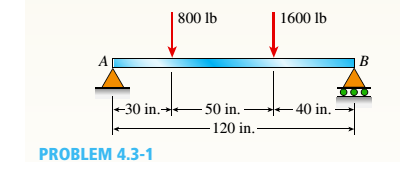
800 lb 1600 lb B -30 in.→-50 in. - 40 in. - 120 in. PROBLEM 4.3-1


Q: A simply supported beam of length 30-in diamater 2-in is supported at A and D, subject to load P at…
A:
Q: A beam ABCD with a vertical arm CE is supported as simple beam at A and D as shown in the figure. A…
A: dear student please rate me positive Stay safe stay happy!
Q: Beam ABCD represents a reinforcedconcretefoundation beam that supports a uniformload of intensity q1…
A: Given Load, q1 = 3500 lb/ft Length, L = 14 ft Find Shear force VB and bending moment MB
Q: 10KN/m 7,5m B (A 15m iom
A: Objective: To calculate normal force, shear force, and bending moment about point D.
Q: P=80 N q=10 N/m B 100 느=40 m --=40 m 2 2
A: The given beam is shown below – Calculating reaction at support at A and B,
Q: 5N 0.5 N/m B 6 m.- - 6 m. - 6 m. - 6 m.- 1. A force of 5 N acts from point D on the beam carrying a…
A:
Q: The cantilever beam with variable stiffness shown in the figure is under the effect of the M…
A:
Q: 4.5-18 Beam ABCwith an overhang at one end supports a partial uniform load of intensity 12 kN/m and…
A:
Q: The embedded cone of height h and circular base (radius R) in the figure is subjected to the strut…
A: Axial force, shear forces, bending moments and torsional moments due to the loading needs to be…
Q: 3000 N/m (3) The beam AB shown in the figure supports a uniform load of intensity 3000 N/m acting…
A: Explanation: ◆ Before drawing SFD and BMD, we need to find the intensity of uniformly distributed…
Q: 4.3-10 Under cruising conditions, the distributed load aeting on the wing of a small airplane has…
A:
Q: The simple beam ACB shown in the figure is subjected to a concentrated load P 30 kips and a…
A: Given: Distributed load (q)=3kips/ftConcentrated load (P)=30kips
Q: A simply supported beam AB supports a trapezoid ally distributed load (see figure). The intensity of…
A: →First calculating Reactions:∑MB=0⇒RA(4)−25(4)42−25×42×2×43=0⇒RA=83.33kN+↑…
Q: 4.3-5 Consider the beam with an overhang shown in the figure. (a) Determine the shear force Vand…
A:
Q: 5.5-12 A small dam of height h = 2.0 m is constructed of vertical wood beams AB of thickness t = 120…
A:
Q: Abeam with a rectangular cross section is simply supported and loaded at its center with a force P.…
A:
Q: The distributed load on the T-section beam in the figure is w = 100 kN/m. The tensile stress that…
A: Bending stress in beams When external load acts on beam shear force and bending moment are set up at…
Q: 4.3-4 Calculate the shear force Vand bending moment M at a cross section located just right of the 4…
A:
Q: A beam has a cross-sectional area as shown in the first figure. The lõàdš on the Bea moment diagram…
A:
Q: Consider the beam shown in the figure. Suppose that the distributed load w = 650 lb/ft . Follow the…
A: Solution ; As the loading is symmetric, so reaction at the support will be equal :…
Q: The cross-section of beam shown in Figure Q2 (centroid in red) is subjected to pure bending. Taking…
A:
Q: 4.3-2 Determine the shear force V and bending moment M just right of the 6 kN load on the simple…
A:
Q: 4.5-6 The simple beam AB shown in the figure is subjected to a concentrated load P and a clockwise…
A:
Q: Develop the general equations for transverse shear stress in the web and flanges of the I-beam…
A:
Q: The simply supported beam is subjected to the loading and has cross-sectional area as in the figure…
A: Draw a free-body diagram of a given beam. Apply force equilibrium in a vertical direction.…
Q: Question contains a hinge in the middle. Find the shear force and the bending moment at the Figure 3…
A:
Q: A railroad tie (or sleeper) is subjected to two rail loads, each of magnitude P = 165 kN, acting as…
A:
Q: H.W.1 /The cantilever beam in Figure below has a rectangular cross section with dimension (20…
A:
Q: The cantilever beam AB shown in the figure is subjected to a uniform load acting throughout one-half…
A: GIVEN DATA A CANITILVER BEAM IS GIVEN
Q: 7) Consider the beam in the figure below. Take w=50 kN/m. The 40 kN force makes an angle of 60…
A:
Q: The simply supported beam AB is subjected to two concentrated load as shown in figure. Determine:…
A:
Q: Q2) A rectangular beam 120mm wide by 400mm deep is loaded as shown in the figure. Find "P" to cause…
A: Any action that can change the state of motion is force. Force is described by its magnitude, point…
Q: he beam ABCD shown in the figure has overhangs that extend in both directions for a distance of 4.2m…
A: In the given problem, initially supports will be replaced by reactions and same will be determined.…
Q: Half of the beam section shown in the figure is made of aluminum (E) and the other half is made of…
A:
Q: The overhanging beam ABC in Figure supports a concentrated load and a uniformly distributed load.…
A:
Q: The beam in the figure below is made from three boards nailed together as shown, If the internal…
A:
Q: 3. For the beam shown below, let wo = 90 N/m and w1 50 N/m. %D Wo | A B -2 m-2 m+3 m 3 m- -2 m…
A:
Q: Draw the shear-force and bending-momentdiagrams for beam AB with a sliding support at Aand an…
A: Shear force is the algebraic sum of the vertical forces at any segment of a beam to the right or…
Q: Ql: A beam with overhang is supported and loaded as shown in Figure. Draw the shear force and the…
A: The free-body diagram of the beam is shown below. Here, HA, VA, and VD are the reactions at the…
Q: 4.5-6 The simple beam AB shown in the figure receives a concentrated load P and a clockwise dominant…
A:
Q: The figure shows a propped up horizontal cantilever beam carrying a 1kN load at the end. The shear…
A: To determine the value of shear force in segment BC.
Q: 5 kN/m 3 cm Q.3 Find the maximum compression and tension beam stress for the cross section as figure…
A: The center of gravity of the given figure is calculated as: y=A1y1+A2y2A1+A2 here, A1 represents…
Q: Calculate the shear force V (in kN) and bending moment M (in kN - m) at a cross section located just…
A:
Q: Q4: If the T- cross section of the beam shown in the Figure (3) below has bending stress of 37 MN/m?…
A:
Q: O. No. 1: A rectangular beam with cross-sectional dimensions b-40 mm and h- 55 mm is subjected to a…
A: As per bartleby guidelines i can solve only one question at one time. kindly upload second question…
Q: Problem 4: A barge shown in the figure carries 290kN/m and 580KN/m loads. 3m 6m Зт 580 kN/m a. Find…
A: The given beam is as shown below, Let the upward load acting on the beam is w, (a) Balancing…
Q: Beam ABC with an overhang at one end supports a partial uniform load of intensity 12 kN/m and a…
A: Given:
Q: A beam having a cross section in the formof a channel (see figure) is subjected to a bendingmoment…
A: Given Beam ratio = 7:3 To find Magnitude of t
Q: Q: For the cantilever beam with uniformly distributed load shown in Figure find; a The maximum shear…
A: As per company policy, we are restricted to solve only the first three sub-part of one question at a…
Calculate the shear force Vand bending moment Mata cross sectionjust to the right of the 800 lb load acting on the simple beam AB shown in the figure.


Trending now
This is a popular solution!

Step by step
Solved in 2 steps with 2 images


- A plane frame with a pin support at A and roller supports at C and £ has a cable attached at E. which runs over Frictionless pulleys al D and B (see figure). The cable force is known to be 400 N. There is a pin connection just Lo the left of joint C. (a) Find reactions at supports^, C, and E. (b) Find internal stress, resultants N, V, and M just to the right of joint C. (c) Find resultant force in the pin near C.A safety valve on the top of a tank containing steam under pressure p has a discharge hole of diameter d(see figure). The valve is designed to release the steam when the pressure reaches the value Pmax If the natural length of the spring, is L and its stiffness is k, what should be the dimension ft of the valve? (Express your result as a formula for h.)Solve the preceding problem for sx= 11 MPa and ??y= -20 MPa (see figure).
- A hollow circular pipe (see figure} support s a load P that is uniformly distributed around a cap plate at the top of the lower pipe. The inner and outer diameters of the upper and lower parts of the pipe are d1= 50 mm, d2= 60 mm, rf3 = 57 mm, and d1= 64 mm, respectively. Pipe lengths are Lt= 2 m and L, = 3 m. Neglect the self-weight of the pipes. Assume that cap plate thickness is small compared to I, and E,. Let E = 110 MPa. (a) If the tensile stress in the upper part is d = 10.5 MPa. what is load PI Also, what are reactions ft, at the upper support and R-, at the lower support? What is the stress ar(MPa) in the lower part? (b) Find displacement S(mm) at the cap plate. Plot the axial force diagram (AFD) [Ar(.f)] and axial displacement diagram (ADD)[5(.t)]. (c) Add the uniformly distributed load q along the censorial axis of pipe segment 2. Find q (kN/m) so that It, = 0. Assume that load P from part (a) is also applied.Two separate cables AC and BC support a sign structure of weight W = 1575 lb attached to a building. The sign is also supported by a pin support at O and a lateral restraint in the '-direction at D. (a) Find the tension in each cable. Neglect the mass of the cables. (b) Find the average stress in each cable if the area of each cable is Ae= 0.471 in2.: A hollow, pressurized sphere having a radius r = 4.8 in, and wall thickness t = 0.4 in. is lowered into a lake (see figure). The compressed air in the tank is at a pressure of 24 psi (gage pressure when the tank: is out of the water). At what depth D0will the wall of the tank be subjected to a compressive stress of 90 psi?
- Solve the preceding problem if F =90 mm, F = 42 kN, and t = 40°MPaA cylindrical brick chimney of height H weighs w = 825 lb/ft of height (see figure). The inner and outer diameters are d1= 3 ft and d2= 4 ft, respectively. The wind pressure against the side of the chimney is p = 10 lb/ft2 of projected area. Determine the maximum height H if there is to be no tension in the brickwork.A mountain bike is moving along a flat path at constant velocity. At some instant, the rider (weight = 670 N) applies pedal and hand forces, as shown in the figure part a. (a) Find reaction forces at the front and rear hubs. (Assume that the bike is pin supported at the rear hub and roller supported at the front hub.) (b) Find internal stress resultants N, V, and M in the inclined seat post (see figure part b
- Solve the preceding problem for the following data: b = 8.0 in., k = 16 lb/in., a = 45°, and P = 10 lb.A long re Lai nine: wall is braced by wood shores set at an angle of 30° and supported by concrete thrust blocks, as shown in the first part of the figure. The shores are evenly spaced at 3 m apart. For analysis purposes, the wall and shores are idealized as shown in the second part of the figure. Note that the base of the wall and both ends of the shores are assumed to be pinned. The pressure of the soil against the wall is assumed to be triangularly distributed, and the resultant force acting on a 3-meter length of the walls is F = 190 kN. If each shore has a 150 mm X 150 mm square cross section, what is the compressive stressA crane boom of mass 450 leg with its center of mass at C is stabilized by two cables AQ and BQ (Ae= 304 mm2 for each cable) as shown in the figure. A load P = 20 KN is supported at point D. The crane boom lies in the y-z plane. (a) Find the tension forces in each cable: TAQand TBQ(kN}. Neglect the mass of the cables, but include the mass of the boom in addition to load P. (b) Find the average stress (s) in each cable.