
Concept explainers
Videos
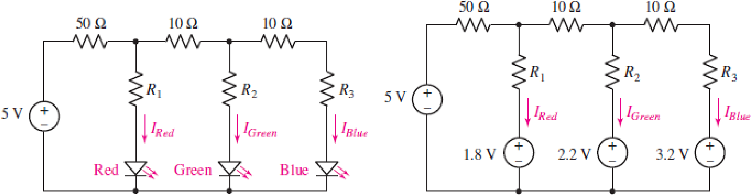
Consider the LED circuit containing a red, green, and blue LED as shown in Fig. 4.89. The LEDs behave much like a voltage source resulting in the circuit in Fig. 4.89, where the light output from each LED will be proportional to the current flowing through the LED. (a) Calculate the current flowing through each LED (IRed, IGreen, and IBlue) if R1 = R2 = R3 = 100 Ω. (b) Determine the resistor values R1, R2, and R3 needed to ensure that the LEDs each have a current of 4 mA flowing through them.
FIGURE 4.89
(a)
Find the current flowing through the each LED in the circuit of Figure 4.89.
Answer to Problem 72E
The current flowing through the each LED in the circuit are
Explanation of Solution
Given data:
Refer to Figure 4.89 in the textbook.
Calculation:
The given circuit is redrawn as shown in Figure 1.
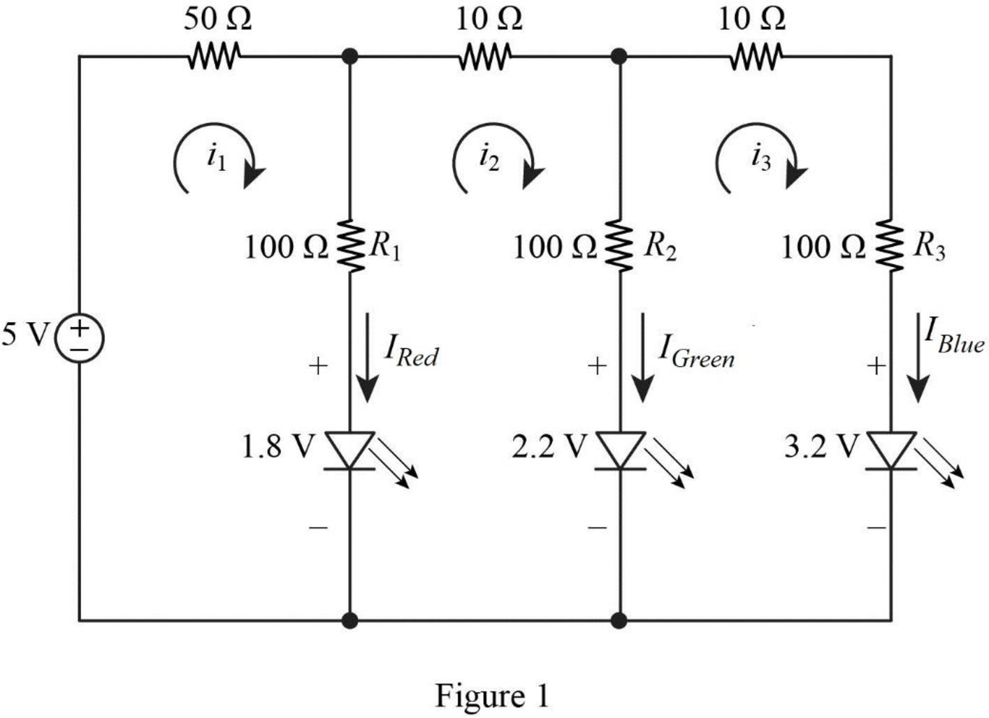
Apply Kirchhoff’s voltage law for loop current
Apply Kirchhoff’s voltage law for loop current
Apply Kirchhoff’s voltage law for loop current
Rearrange the equation (3) as follows,
Substitute equation (4) in equation (1).
Reduce the equation as follows,
Substitute equation (4), (5) in equation (2) to find the current
Reduce the equation as follows,
Substitute
Substitute
In Figure 1, the current
Substitute
In Figure 1, the current
Substitute
In Figure 1, the current
Substitute
Conclusion:
Thus, the current flowing through the each LED in the circuit are
(b)
Find the resistance values of
Answer to Problem 72E
The resistance values of
Explanation of Solution
Given data:
The current,
Calculation:
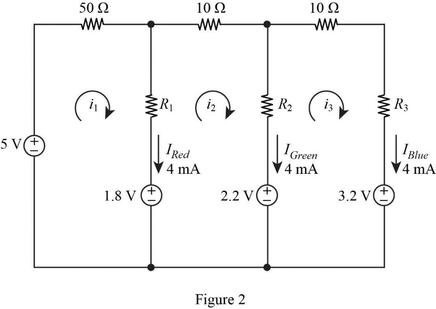
The given circuit is redrawn as shown in Figure 2.
Refer to Part (a),
Substitute
Substitute
Substitute
Apply Kirchhoff’s voltage law for loop current
Substitute
Reduce the equation as follows,
Apply Kirchhoff’s voltage law for loop current
Substitute
Reduce the equation as follows,
Apply Kirchhoff’s voltage law for loop current
Substitute
Reduce the equation as follows,
Conclusion:
Thus, the resistance values of
Want to see more full solutions like this?
Chapter 4 Solutions
Loose Leaf for Engineering Circuit Analysis Format: Loose-leaf
Additional Engineering Textbook Solutions
Programmable Logic Controllers
Electric Circuits (10th Edition)
Electric Circuits. (11th Edition)
Principles and Applications of Electrical Engineering
Basic Engineering Circuit Analysis
Microelectronics: Circuit Analysis and Design


- The system of using helicopters to work on live power lines is based on the principle that electrical current seeks to flow into the ground. Select one: True Falsearrow_forwardThe sun’s output power is given as 1000 W/m2. The solar module has a surface area of 1 m^2 with a conversion efficiency of 10%. A charge controller converts the 20V module voltage to 12V battery voltage, with an efficiency of 84% The battery is 12V with a capacity of 10Ah. Assuming the battery is half empty and the bulb is powered on, how long will it take for the battery to be fully charged? How long can the bulb be powered at night, assuming full battery when the sun goes down and that you can fully drain the batteryarrow_forwardFind the Norton equivalent for the circuit in Fig. 4.129arrow_forward
- Design a charger circuit for mobile phone from:a. 220V, 50Hz AC sourceb. 1.5 V AA BatterySelect the proper circuit topologies and components. (please explain in detail)arrow_forwardObjectives: Voltage drop measurements using resistors connected in series. The relationship between resistance value and voltage drop (Kirchhoff’s Second Law) Circuit components: 1 Plug-in board, DIN A4 576 74 1 STE resistor, 100 W, 2 W, 5% 577 32 1 STE resistor, 150 W, 2 W, 5% 577 34 1 STE resistor, 1 kW, 2 W, 5% 577 44 Power Supply: 1 AC/DC stabilizer 726 88 Connectors: 3 Pairs of connecting leads, red/blue, 50 cm 501 45 1 Set of 10 bridging plugs 501 48 Measurement Instruments: 1 Voltmeter, 10 V DC 1 Amperemeter, 10 mA DC Measuring the voltage drop across resistors…arrow_forwardTeaching values through exhortation can be done with the help of ____________ a. Friends b. Computers c. Neighbors d. Stories with moral lessonsarrow_forward
- 4.70 Determine the maximum power delivered to the variable resistor R shown in the circuit of Fig. 4.136.arrow_forwardA black box with a circuit in it is connected to a variable resistor. An ideal ammeter (with zero resistance) and an ideal voltmeter (with infinite resistance) are used to measure current and voltage as shown in Fig. 4.143.arrow_forwardThe human body has many biological system that can be modelled mathematically. Some of these systems are open-loop others are closed loop. Your final report should consider a mathematical model of one of these systems.arrow_forward
 Introductory Circuit Analysis (13th Edition)Electrical EngineeringISBN:9780133923605Author:Robert L. BoylestadPublisher:PEARSON
 Delmar's Standard Textbook Of ElectricityElectrical EngineeringISBN:9781337900348Author:Stephen L. HermanPublisher:Cengage Learning
 Programmable Logic ControllersElectrical EngineeringISBN:9780073373843Author:Frank D. PetruzellaPublisher:McGraw-Hill Education
 Fundamentals of Electric CircuitsElectrical EngineeringISBN:9780078028229Author:Charles K Alexander, Matthew SadikuPublisher:McGraw-Hill Education
 Electric Circuits. (11th Edition)Electrical EngineeringISBN:9780134746968Author:James W. Nilsson, Susan RiedelPublisher:PEARSON
 Engineering ElectromagneticsElectrical EngineeringISBN:9780078028151Author:Hayt, William H. (william Hart), Jr, BUCK, John A.Publisher:Mcgraw-hill Education,