
Concept explainers
Videos
(a)
The reaction at
(a)
Answer to Problem 4.24P
The reaction at
Explanation of Solution
Take
Let
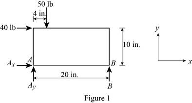
The free body diagram is sketched below as figure 1.
Here,
Write the expression for the moment at
Here,
Above equation implies that net moment at any point is the sum of product of each force acting on the system and perpendicular distance of the force and the point.
The moment at
Thus, the complete expression of
Here,
At equilibrium, the sum of the moment acting at
Write the expression for the net force along the
Here,
At equilibrium, the net force along the
Write the expression for the net force along the
Here,
At equilibrium, the net force along the
Let
Write the expression for the magnitude of net reaction at
Here,
Therefore, write the expression for the
Calculation:
Rearrange equation (III) to get
From figure 1, the reaction
Rearrange equation (V) to get
The
Rearrange equation (VII) to get
Substitute
Substitute
Substitute
Therefore, the reaction at
(b)
The reaction at
(b)
Answer to Problem 4.24P
The reaction at
Explanation of Solution
Take vectors along positive
Let
The free body diagram is sketched below as figure 1.

Here,
Write the expression for the moment at
Here,
Above equation implies that net moment at any point is the sum of product of each force acting on the system and perpendicular distance of the force and the point.
The moment at
Thus, the complete expression of
Here,
At equilibrium, the sum of the moment acting at
Write the expression for the net force along the
Here,
At equilibrium, the net force along the
Write the expression for the net force along the
Here,
At equilibrium, the net force along the
Let
Write the expression for the magnitude of net reaction at
Here,
Therefore, write the expression for the
Calculation:
Rearrange equation (III) to get
From figure 1, the reaction
Rearrange equation (V) to get
Substitute
The
Rearrange equation (VII) to get
Substitute
Substitute
Substitute
Therefore, the reaction at
Want to see more full solutions like this?
Chapter 4 Solutions
Vector Mechanics for Engineers: Statics and Dynamics


- For each of the plates and loadings shown, determine the reactions at A and Barrow_forwardTwo transmission belts pass over a double-sheaved pulley that is attached to an axle supported by bearings at A and D . The radius of the inner sheave is 125 mm and the radius of the outer sheave is 250 mm. Knowing that when the system is at rest, the tension is 90 N in both portions of belt B and 150 N in both portions of belt C , determine the reactions at A and D . Assume that the bearing at D does not exert any axial thrust.arrow_forwardKnowing that the pulley has a radius of 75 mm, determine the components of the reactions at A and B.arrow_forward
- A thin ring with a mass of 2 kg and radius r = 140 mm is held against a frictionless wall by a 125-mm string AB . Determine (a) the distance d, (b) the tension in the string, (c) the reaction at C.arrow_forward4. Determine the reaction at C, if a horizontal circular platform of radius "R" is supported at three points A, B, C on its circumference. A and B are 90° apart and C is 120° from A. The platform carries a vertical load of 400 kN at its center and one of 100 kN at a point D on the circumference diametrically opposite Aarrow_forwardTwo 9-in.-diameter pipes (pipe 1 and pipe 2) are supported every 7.5 ft by a small frame like that shown. Knowing that the combined weight of each pipe and its contents is 30 lb/ft and assuming frictionless surfaces, determine the components of the reactions at A and G.arrow_forward
- Knowing that the pulley has a radius of 75 mm, determine the componentsof the reactions at A and B.arrow_forwardA 20-kg ladder used to reach high shelves in a storeroom is supported by two flanged wheels A and B mounted on a rail and by a flangeless wheel C resting against a rail fixed to the wall. An 80-kg man stands on the ladder and leans to the right. The line of action of the combined weight W of the man and ladder intersects the floor at point D. Determine the reactions at A, B, and C.arrow_forwardThe L-shaped member ACB is supported by a pin and bracket at C and by an inextensible cord attached at A and B and passing over a frictionless pulley at D. The tension may be assumed to be the same in portions AD and BD of the cord. If the magnitudes of the forces applied at A and B are, respectively, P = 25 lb and Q = 0, determine (a) the tension in the cord, (b) the reaction at Carrow_forward
- The axis of the three-hinge arch ABC is a parabola with vertex at B . Knowing that P= 112 kN and Q = 140 kN, determine (a) the components of the reaction at A, (b) the components of the force exerted at B on segment AB.arrow_forwardThe axis of the three-hinge arch ABC is a parabola with vertex at B.Knowing that P= 112 kN and Q =140 kN, determine (a) the components of the reaction at A, (b) the components of the force exerted at B on segment AB.arrow_forwardThe press shown is used to emboss a small seal at E. Knowing that P= 250 N, determine (a) the vertical component of the force exerted on the seal, (b) the reaction at A.arrow_forward
 Elements Of ElectromagneticsMechanical EngineeringISBN:9780190698614Author:Sadiku, Matthew N. O.Publisher:Oxford University Press
 Mechanics of Materials (10th Edition)Mechanical EngineeringISBN:9780134319650Author:Russell C. HibbelerPublisher:PEARSON
 Thermodynamics: An Engineering ApproachMechanical EngineeringISBN:9781259822674Author:Yunus A. Cengel Dr., Michael A. BolesPublisher:McGraw-Hill Education
 Control Systems EngineeringMechanical EngineeringISBN:9781118170519Author:Norman S. NisePublisher:WILEY
 Mechanics of Materials (MindTap Course List)Mechanical EngineeringISBN:9781337093347Author:Barry J. Goodno, James M. GerePublisher:Cengage Learning
 Engineering Mechanics: StaticsMechanical EngineeringISBN:9781118807330Author:James L. Meriam, L. G. Kraige, J. N. BoltonPublisher:WILEY