
Concept explainers
Videos
A truss can be supported in the eight different ways shown A connections consist of smooth pins, rollers, or short links. For case, answer the questions listed in Prob. 4.59, and, wherever possible, compute the reactions, assuming that the magnitude force P is 12 kips.
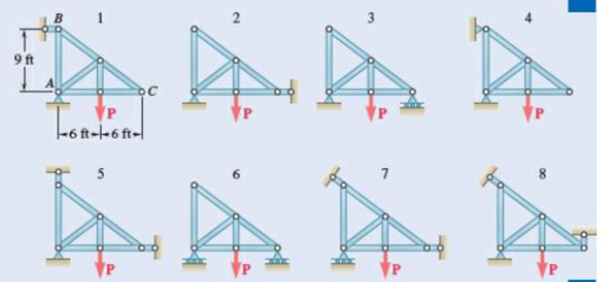
Fig. P4.60
(a)
Find whether the plate is completely, partially, or improperly constrained.
Answer to Problem 4.60P
The plate in figure 1 is
The plate figure 2 is
The plate figure 3 is
The plate figure 4 is
The plate figure 5 is
The plate figure 6 is
The plate figure 7 is
The plate figure 8 is
Explanation of Solution
Given information:
The magnitude of the force P is 12 kips.
Calculation:
Figure 1:
Show the free-body diagram of the Figure 1.
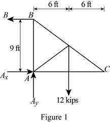
The three reactions in the plate behave like non-concurrent and non-parallel force system.
The plate in figure 1 is
Figure 2:
Show the free-body diagram of the Figure 2.
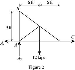
The three reactions in the plate behave like concurrent force system.
The plate figure 2 is
Figure 3:
Show the free-body diagram of the Figure 3.
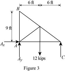
The three reactions in the plate behave like non-concurrent and non-parallel force system.
The plate figure 3 is
Figure 4:
Show the free-body diagram of the Figure 4.
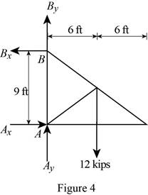
The four reactions in the plate behave like non-concurrent and non-parallel force system.
The plate figure 4 is
Figure 5:
Show the free-body diagram of the Figure 5.
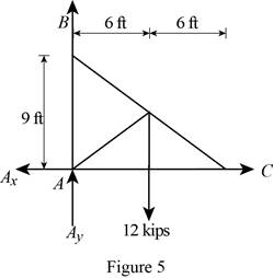
The four reactions in the plate behave like concurrent force system.
The plate figure 5 is
Figure 6:
Show the free-body diagram of the Figure 6.
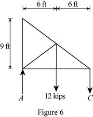
The two reactions in the plate behave like concurrent force system.
The plate figure 6 is
Figure 7:
Show the free-body diagram of the Figure 7.
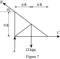
The three reactions in the plate behave like non-concurrent and non-parallel force system.
The plate figure 7 is
Figure 8:
Show the free-body diagram of the Figure 8.
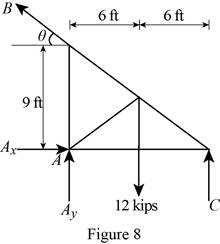
The four reactions in the plate behave like non-concurrent and non-parallel force system.
The plate figure 8 is
(b)
Find whether the reactions are statically determinate or indeterminate.
Answer to Problem 4.60P
The reactions in figure 1 is
The reactions in figure 2 is
The reactions in figure 3 is
The reactions in figure 4 is
The reactions in figure 5 is
The reactions in figure 6 is
The reactions in figure 7 is
The reactions in figure 8 is
Explanation of Solution
Refer Figure 1:
The equilibrium equations are;
The equilibrium equations are enough to determine the unknown reactions.
The reactions in figure 1 is
Refer Figure 2:
The equilibrium equations are;
The equilibrium equations are enough to determine the unknown reactions.
But the plate is improperly constrained and the plate is not in equilibrium.
The reactions in figure 2 is
Refer Figure 3:
The equilibrium equations are;
The equilibrium equations are enough to determine the unknown reactions.
The reactions in figure 3 is
Refer Figure 4:
The equilibrium equations are;
The equilibrium equations are not enough to determine the unknown reactions.
The reactions in figure 4 is
Refer Figure 5:
The equilibrium equations are;
The equilibrium equations are enough to determine the unknown reactions.
But the plate is improperly constrained and the plate is not in equilibrium.
The reactions in figure 5 is
Refer Figure 6:
The equilibrium equations are;
The equilibrium equations are enough to determine the unknown reactions.
The reactions in figure 6 is
Refer Figure 7:
The equilibrium equations are;
The equilibrium equations are enough to determine the unknown reactions.
The reactions in figure 7 is
Refer Figure 8:
The equilibrium equations are;
The equilibrium equations are not enough to determine the unknown reactions.
The reactions in figure 8 is
(c)
Find whether the equilibrium of the plate is maintained.
Answer to Problem 4.60P
The reactions in the plate 1 are
The plate 1 is in
The plate 2 is in
The reactions in the plate 3 are
The plate 3 is in
The reactions in the plate 4 are
The plate 4 is in
The plate 5 is in
The reactions in the plate 6 are
The plate 6 is in
The reactions in the plate 7 are
The plate 7 is in
The reactions in the plate 8 are
The plate 8 is in
Explanation of Solution
Refer Figure 1:
The equilibrium equations are;
Take moment about point A.
Resolve the horizontal component of forces.
Resolve the vertical component of forces.
Find the resultant force at A;
Find the angle
Therefore, the reactions in the plate 1 are
The plate 1 is in
Refer Figure 2:
The equilibrium equations are;
The moment about point A is not equal to zero.
The plate 2 is in
Refer Figure 3:
The equilibrium equations are;
Take moment about point A.
Resolve the horizontal component of forces.
Resolve the vertical component of forces.
Therefore, the reactions in the plate 3 are
The plate 3 is in
Refer Figure 4:
The equilibrium equations are;
Take moment about point A.
Resolve the horizontal component of forces.
Resolve the vertical component of forces.
Therefore, the reactions in the plate 4 are
The plate 4 is in
Refer Figure 5:
The equilibrium equations are;
The moment about point A is not equal to zero.
The plate 5 is in
Refer Figure 6:
The equilibrium equations are;
Take moment about point A.
Resolve the vertical component of forces.
Therefore, the reactions in the plate 6 are
The plate 6 is in
Refer Figure 7:
The equilibrium equations are;
Find the angle
Take moment about point A.
Resolve the horizontal component of forces.
Resolve the vertical component of forces.
Therefore, the reactions in the plate 7 are
The plate 7 is in
Refer Figure 8:
The equilibrium equations are;
Take moment about point C.
Therefore, the reactions in the plate 8 are
The plate 8 is in
Want to see more full solutions like this?
Chapter 4 Solutions
Vector Mechanics for Engineers: Statics and Dynamics


- A 20-kg ladder used to reach high shelves in a storeroom is supported by two flanged wheels A and B mounted on a rail and by a flangeless wheel C resting against a rail fixed to the wall. An 80-kg man stands on the ladder and leans to the right. The line of action of the combined weight W of the man and ladder intersects the floor at point D. Determine the reactions at A, B, and C.arrow_forwardA 100-kg uniform rectangular plate is supported in the position shown by hinges A and B and by cable DCE that passes over a frictionless hook at C . Assuming that the tension is the same in both parts of the cable, determine (a) the tension in the cable, (b) the reactions at A and B . Assume that the hinge at B does not exert any axial thrust.arrow_forwardA uniform circular rod of weight 8 lb and radius 10 in. is attached to a pin at C and to the cable AB. Determine (a) the tension in the cable,(b) the reaction at C.arrow_forward
- A force P of magnitude 90 lb is applied to member ACDE that is supported by a frictionless pin at D and by the cable ABE . Since the cable passes over a small pulley at B , the tension may be assumed to be the same in portions AB and BE of the cable. For the case when a= 3 in., determine (a) the tension in the cable, (b) the reaction at D.arrow_forwardThe press shown is used to emboss a small seal at E. Knowing that the vertical component of the force exerted on the seal must be 900 N, determine (a) the required vertical force P,(b) the corresponding reaction at A.arrow_forwardA 2.4-m boom is held by a ball-and-socket joint at C and by two cables AD and AE . Determine the tension in each cable and the reaction at C.arrow_forward
- The bent rod ABEF is supported by bearings at C and D and by wire AH . Knowing that portion AB of the rod is 250 mm long, determine (a) the tension in wire AH, ( b) the reactions at C and D . Assume that the bearing at D does not exert any axial thrust.arrow_forward4.108 - A 2250 N marquee, 2,4 x 3 m, is held in a horizontal position bytwo horizontal hinges at A and B and by a cable CD attached to a point D located 1,5m directly above B. Determine the tension in the cable and the components of the reactions at the hinges.arrow_forwardTwo 9-in.-diameter pipes (pipe 1 and pipe 2) are supported every 7.5 ft by a small frame like that shown. Knowing that the combined weight of each pipe and its contents is 30 lb/ft and assuming frictionless surfaces, determine the components of the reactions at A and G.arrow_forward
- A 600-lb crate hangs from a cable that passes over a pulley B and is attached to a support at H. The 200-lb boom AB is supported by a ball-and-socket joint at A and by two cables DE and DF. The center of gravity of the boom is located at G. Determine (a) the tension in cables DE and DF, (b) the reaction at A.arrow_forwardThe L-shaped member ACB is supported by a pin and bracket at C and by an inextensible cord attached at A and B and passing over a frictionless pulley at D. The tension may be assumed to be the same in portions AD and BD of the cord. If the magnitudes of the forces applied at A and B are, respectively, P = 25 lb and Q = 0, determine (a) the tension in the cord, (b) the reaction at Carrow_forward4. Determine the reaction at C, if a horizontal circular platform of radius "R" is supported at three points A, B, C on its circumference. A and B are 90° apart and C is 120° from A. The platform carries a vertical load of 400 kN at its center and one of 100 kN at a point D on the circumference diametrically opposite Aarrow_forward
 Elements Of ElectromagneticsMechanical EngineeringISBN:9780190698614Author:Sadiku, Matthew N. O.Publisher:Oxford University Press
 Mechanics of Materials (10th Edition)Mechanical EngineeringISBN:9780134319650Author:Russell C. HibbelerPublisher:PEARSON
 Thermodynamics: An Engineering ApproachMechanical EngineeringISBN:9781259822674Author:Yunus A. Cengel Dr., Michael A. BolesPublisher:McGraw-Hill Education
 Control Systems EngineeringMechanical EngineeringISBN:9781118170519Author:Norman S. NisePublisher:WILEY
 Mechanics of Materials (MindTap Course List)Mechanical EngineeringISBN:9781337093347Author:Barry J. Goodno, James M. GerePublisher:Cengage Learning
 Engineering Mechanics: StaticsMechanical EngineeringISBN:9781118807330Author:James L. Meriam, L. G. Kraige, J. N. BoltonPublisher:WILEY