
Concept explainers
Videos
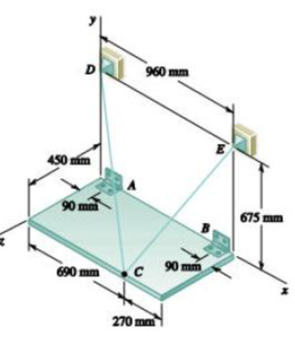
PROBLEM 4.117
A 100-kg uniform rectangular plate is supported in the position shown by hinges A and B and by cable DCE that passes over n frictionless hook at C. Assuming that the tension is the same in both parts of the cable, determine (a) the tension in the cable, (b) the reactions at A and B. Assume that the hinge at B does not exert any axial thrust.
(a)
The tension on the cable.
Answer to Problem 4.117P
The tension on the cable is
Explanation of Solution
The tension in the cable
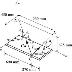
Figure 1
The position vector of the point
The position vector of the point
The position vector of the point
The vector
The tension across the cable from
Here,
Substitute
The tension across the cable from
Here,
Substitute
The weight is given as,
Here,
Substitute
The force on the point is zero. This means that the sum of the moments of the force will also be zero.
Here,
Substitute the vector values and determine the cross product.
Conclusion:
Equate the coefficients of
Therefore, the tension on the cable is
(b)
The reactions at
Answer to Problem 4.117P
The reactions at
Explanation of Solution
The free body diagram of the given arrangement is given in Figure 1.
Equate the coefficients of
Equate the coefficients of
The net force acting on the point is zero.
Here,
Substitute
Equate the coefficients of
Equate the coefficients of
Equate the coefficients of
Conclusion:
From (II) and (III) the vector
And, from (V), (VI) and (VII) the vector
Therefore, the reactions at
Want to see more full solutions like this?
Chapter 4 Solutions
Vector Mechanics for Engineers: Statics


- A 20-kg ladder used to reach high shelves in a storeroom is supported by two flanged wheels A and B mounted on a rail and by a flangeless wheel C resting against a rail fixed to the wall. An 80-kg man stands on the ladder and leans to the right. The line of action of the combined weight W of the man and ladder intersects the floor at point D. Determine the reactions at A, B, and C.arrow_forwardTwo 9-in.-diameter pipes (pipe 1 and pipe 2) are supported every 7.5 ft by a small frame like that shown. Knowing that the combined weight of each pipe and its contents is 30 lb/ft and assuming frictionless surfaces, determine the components of the reactions at A and G.arrow_forwardThe uniform 10-kg rod AB is supported by a ball-and-socket joint at A and by the cord CG that is attached to the midpoint G of the rod. Knowing that the rod leans against a frictionless vertical wall at B , determine (a) the tension in the cord, (b) the reactions at A and B.arrow_forward
- A force P of magnitude 90 lb is applied to member ACDE that is supported by a frictionless pin at D and by the cable ABE . Since the cable passes over a small pulley at B , the tension may be assumed to be the same in portions AB and BE of the cable. For the case when a= 3 in., determine (a) the tension in the cable, (b) the reaction at D.arrow_forwardA 2.4-m boom is held by a ball-and-socket joint at C and by two cables AD and AE . Determine the tension in each cable and the reaction at C.arrow_forwardA uniform rod AB with a length of l and weight of W is suspended from two cords AC and BC of equal length. Determine the angle 0 corresponding to the equilibrium position when a couple M is applied to the rod.arrow_forward
- The press shown is used to emboss a small seal at E. Knowing that the vertical component of the force exerted on the seal must be 900 N, determine (a) the required vertical force P,(b) the corresponding reaction at A.arrow_forwardA 48-in. boom is held by a ball-and-socket joint at C and by two cables BF and DAF passes around a frictionless pulley at A . For the loading shown, determine the tension in each cable and the reaction at C.arrow_forwardTwo forces P and Q are applied as shown to an aircraft connection. Knowing that the connection is in equilibrium and that P = 500 lb and Q= 650 lb, determine the magnitudes of the forces exerted on rods A and B.arrow_forward
- Solve Prob. 4.106 for a = 1.5 m.(Reference to problem 4.106):The 6-m pole ABC is acted upon by a 455-N force as shown. The pole is held by a ball-and-socket joint at A and by two cables BD and BE. For a = 3 m, determine the tension in each cable and the reaction at A.arrow_forwardThe T-shaped bracket shown is supported by a small wheel at E and pegs at C and D . Neglecting the effect of friction, determine (a) the smallest value of 0 for which the equilibrium of the bracket is maintained, (b) the corresponding reactions at C, D, and E.arrow_forwardA foldable tray for the paper supply of a photocopy machine is shown. The tray is supported by a single hinge at A and two slotted links (one on each side of the tray). If the stack of paper weighs 14 N and other weights may be neglected, determine the reactions at point B for one of the links when D = 190 mm.arrow_forward
 Elements Of ElectromagneticsMechanical EngineeringISBN:9780190698614Author:Sadiku, Matthew N. O.Publisher:Oxford University Press
 Mechanics of Materials (10th Edition)Mechanical EngineeringISBN:9780134319650Author:Russell C. HibbelerPublisher:PEARSON
 Thermodynamics: An Engineering ApproachMechanical EngineeringISBN:9781259822674Author:Yunus A. Cengel Dr., Michael A. BolesPublisher:McGraw-Hill Education
 Control Systems EngineeringMechanical EngineeringISBN:9781118170519Author:Norman S. NisePublisher:WILEY
 Mechanics of Materials (MindTap Course List)Mechanical EngineeringISBN:9781337093347Author:Barry J. Goodno, James M. GerePublisher:Cengage Learning
 Engineering Mechanics: StaticsMechanical EngineeringISBN:9781118807330Author:James L. Meriam, L. G. Kraige, J. N. BoltonPublisher:WILEY