
Videos
4.39 and 4.40 A copper strip (Ec = 105 GPa) and an aluminum strip (Ea = 75 GPa) are bonded together to form the composite beam shown. Knowing that the beam is bent about a horizontal axis by a couple of moment M = 35 N·m, determine the maximum stress in (a) the aluminum strip, (b) the copper strip.
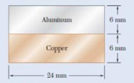
Fig. P4.39
(a)
Find the maximum stress in the aluminum strip.
Answer to Problem 39P
The maximum stress in the aluminum strip is
Explanation of Solution
Given information:
The modulus of elasticity
The modulus of elasticity
The moment (M) in the beam is
Calculation:
Show the cross-section of the composite bar as shown in Figure 1.
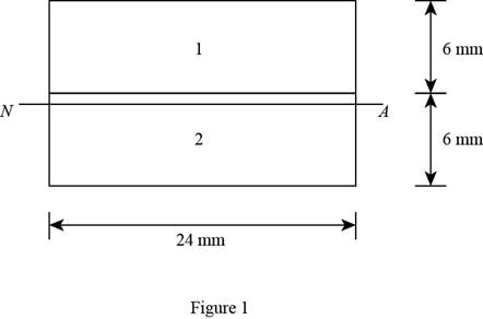
Refer Figure 1.
Consider the Copper and Aluminum is represented by rectangle 2 and 1.
The width and depth of the rectangle 1 are
The width and depth of the rectangle 2 are
Consider Aluminum as the reference material, then the value of
Calculate the ratio
Substitute
Calculate the distance (
Here,
The value of
Substitute
Consider the entire cross-section of the composite bar is transformed into Aluminum.
Calculate the moment of inertia
Substitute
Calculate the moment of inertia
Substitute
Calculate the moment of inertia of the transformed cross-section using the relation:
Substitute
Calculate the maximum stress (
Calculate the maximum stress for Aluminum strip as follows:
Substitute
Thus, the maximum stress in the aluminum strip is
(b)
Find the maximum stress in the aluminum strip.
Answer to Problem 39P
The maximum stress in the aluminum strip is
Explanation of Solution
Given information:
The modulus of elasticity
The modulus of elasticity
The moment (M) in the beam is
Calculation:
Calculate the maximum stress for Copper strip as follows:
Substitute
Thus, the maximum stress in the copper strip is
Want to see more full solutions like this?
Chapter 4 Solutions
Mechanics of Materials, 7th Edition


- A cable AB of span L and a simple beam A'B' of the same span are subjected to identical vertical loadings as shown. Show that the magnitude of the bending moment at a point C' in the beam is equal to the product T0h, where T0 is the magnitude of the horizontal component of the tension force in the cable and h is the vertical distance between point C and the chord joining the points of support A and B.arrow_forwardA rod must not stretch more than 6 mm when the tension in the wire is 8 kN. Knowing that E = 105 GPa and that the maximum allowable normal stress is 150 MPa, determine the corresponding maximum length of the rod (m).arrow_forwardTwo cylindrical rods, one of steel and the other of brass, are joined at C and restrained by rigid supports at A and E. The steel rod has a length of 300 mm while the brass rod has a length of 200 mm. The diameters of the rods are shown in the figure below. A force of 60 kN is applied at point B of the steel segment. For the loading shown and knowing that modulus of elasticity values for steel and brass are respectively Es = 200 GPa and Eb = 105 GPa, determine a.) The reactions at A and E: RA and RE. b.) The deflection of point C from its original location. how to doarrow_forward
- Link AB, of width b =50 mm and thickness t = 6 mm, is used to support the end of a horizontal beam. Knowing that the average normal stress in the link is 2140 MPa, and that the average shearing stress in each of the two pins is 80 MPa, determine (a) the diameter d of the pins, (b) the average bearing stress in the link.arrow_forwardKnowing that for the beam shown the allowable stress is 80 MPa in tension and 100 MPa in compression, determine the largest couple M that can be applied. step by step please!!arrow_forwardA weightlifting bar is loaded symmetrically in A and D (P = 1500N of each side). The weightlifter's hands are located at B and C, 0.45 m from A and D. Determine the maximum bending moment in the bar ABCD and the minimum diameter d of the bar knowing that the constraint admissible for the material of the bar is 200MPa.arrow_forward
- A fabric used in air-inflated structures is subjected to a biaxial load-ing that results in normal stresses σx=120 MPa and σz =160 MPa. Knowing that the properties of the fabric can be approximated as E=87 GPa and ν= 0.34, determine the change in length of (a) side AB, (b) side BC, (c) diagonal AC.arrow_forwardA milling operation was used to remove a portion of a solid bar of square cross section. Knowing that a= 30 mm, d= 20 mm, and σall= 60 MPa, determine the magnitude P of the largest forces that can be safely applied at the centers of the ends of the bar.arrow_forwardThe structure shown consists of a single member ABCDE with a pin support at A and a roller support at E. Points B and D are at the midpoints of their respective segments. Determine the internal shear force acting on I which are located immediately to the left of C. Take N = 1 kN, O = 3 kN, and P = 4 kN.arrow_forward
- Knowing that a beam of the cross section shown is bent about a hori-zontal axis and that the bending moment is 50 kip-in., determine the total force acting (a) on the top flange (b) on the shaded portion of the webarrow_forwardTo determine the state of stress in a solid rod using the principle of superposition. A solid rod has a diameter of e� = 55 mmmm and is subjected to the loading shown. Let a� = 200 mmmm , b� = 220 mmmm , c� = 350 mmmm , d� = 250 mmmm , and P� = 3.0 kNkN . Take point A to be at the top of the circular cross-section. As shown (Figure 2), a cut was made at A to determine the resultant internal loadings. Determine the moment about the x axis, Mx��. b) Part B - Moment about the z axis at A Part C - Stress due to the normal force To find the state of stress at A, the principle of superposition must be used. If the rod has a diameter of 55 mm , find the stress σA�� due to the normal force. Part D - Stress due to the bending moment about the x axis To find the state of stress at A, the principle of superposition must be used. If the rod has a diameter of 55 mm , find the stress σA�� due to the bending moment about the x axis.arrow_forwardDetermine (a) the distance a for which the maximum absolute value of the bending moment in the beam is as small as possible, (b) the corresponding maximum normal stress due to bending.arrow_forward
 Elements Of ElectromagneticsMechanical EngineeringISBN:9780190698614Author:Sadiku, Matthew N. O.Publisher:Oxford University Press
 Mechanics of Materials (10th Edition)Mechanical EngineeringISBN:9780134319650Author:Russell C. HibbelerPublisher:PEARSON
 Thermodynamics: An Engineering ApproachMechanical EngineeringISBN:9781259822674Author:Yunus A. Cengel Dr., Michael A. BolesPublisher:McGraw-Hill Education
 Control Systems EngineeringMechanical EngineeringISBN:9781118170519Author:Norman S. NisePublisher:WILEY
 Mechanics of Materials (MindTap Course List)Mechanical EngineeringISBN:9781337093347Author:Barry J. Goodno, James M. GerePublisher:Cengage Learning
 Engineering Mechanics: StaticsMechanical EngineeringISBN:9781118807330Author:James L. Meriam, L. G. Kraige, J. N. BoltonPublisher:WILEY