
Videos
A short column is made by nailing four 1 × 4-in. planks to a 4 × 4-in. timber. Using an allowable stress of 600 psi, determine the largest compressive load P that can be applied at the center of the top section of the timber column as shown if (a) the column is as described, (b) plank 1 is removed, (c) planks 1 and 2 are removed, (d) planks 1, 2, and 3 are removed, (e) all planks are removed.
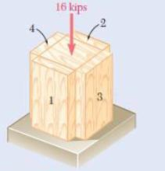
Fig. P4.112
(a)
Find the largest compressive load P that can be applied at the center of the top section of the timber column.
Answer to Problem 112P
The largest compressive load P is
Explanation of Solution
Given information:
The compressive load P is
The allowable stress
The width
The depth
The width
The depth
Calculation:
Sketch the centric loading as shown in Figure 1.
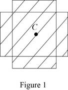
Refer to Figure 1.
Find the area of the timber section using the relation:
Substitute
Calculate the largest compressive load P using the relation:
Substitute
Thus, the largest compressive load P is
(b)
Find the largest compressive load P that can be applied at the center of the top section of the timber column without plank 1.
Answer to Problem 112P
The largest compressive load P that can be applied at the center of the top section of the timber column without plank 1 is
Explanation of Solution
Calculation:
Sketch the Eccentric loading as shown in Figure 2.
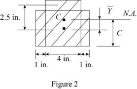
Find the area of the timber section using the relation:
Substitute
Refer to Figure 2.
Find the centroid
Substitute
Refer to Figure 2.
Find the moment of inertia
Substitute
Find the moment of inertia
Substitute
Find the total moment of inertia as follows:
Substitute
Calculate the largest compressive load P that can be applied at the center of the top section of the timber column without plank 1using the relation:
Here, e is the eccentricity, I is the moment of inertia, A is the area of cross section, and c is the distance between the centroid from extreme fibre.
Substitute
Thus, the largest compressive load P that can be applied at the center of the top section of the timber column without plank 1 is
(c)
Find the largest compressive load P that can be applied at the center of the top section of the timber column without plank 1and 2.
Answer to Problem 112P
The largest compressive load P that can be applied at the center of the top section of the timber column without plank 1 and 2 is
Explanation of Solution
Calculation:
Sketch the centric loading as shown in Figure 3.
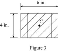
Refer to Figure 3.
Find the area of the timber section using the relation:
Substitute
Calculate the largest compressive load P using the relation:
Substitute
Thus, the largest compressive load P is
(d)
Find the largest compressive load P that can be applied at the center of the top section of the timber column without plank , 2, and 3.
Answer to Problem 112P
The largest compressive load P that can be applied at the center of the top section of the timber column without plank 1, 2, and 3 is
Explanation of Solution
Calculation:
Sketch the Eccentric loading as shown in Figure 4.
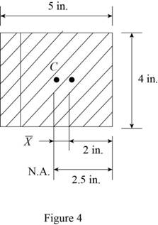
Refer to Figure 4.
Find the area of the timber section using the relation:
Substitute
Find the centroid
Determine the moment of inertia (I) of eccentric section as follows:
Substitute
Calculate the largest compressive load P that can be applied at the center of the top section of the timber column without plank , 2, and 3 using the relation:
Here, e is the eccentricity, I is the moment of inertia, A is the area of cross section, and c is the distance between the centroid from extreme fibre.
Substitute
The largest compressive load P that can be applied at the center of the top section of the timber column without plank 1, 2, and 3 is
(e)
Find the largest compressive load P that can be applied at the center of the top section of the timber all columns are removed.
Answer to Problem 112P
The largest compressive load P that can be applied at the center of the top section of the timber all columns are removed is
Explanation of Solution
Calculation:
Sketch the centric loading as shown in Figure 5.
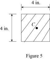
Refer to Figure 5.
Find the area of the timber section using the relation:
Substitute
Calculate the largest compressive load P using the relation:
Substitute
Thus, the largest compressive load P that can be applied at the center of the top section of the timber all columns are removed is
Want to see more full solutions like this?
Chapter 4 Solutions
Mechanics of Materials, 7th Edition


- Two wooden members of uniform cross section are joined by the simple scarf splice shown. Knowing that the maximum allowable tensile stress in the glued splice is 82.4 psi, determine the largest load P that can be safely supported if W = 4.5 in, L = 8.9 in and θ= 55.3arrow_forwardA14-kN tensile load will be applied to a 50-m length of steel wire with E = 200 GPa. Determine the smallest diameter wire that can be used, knowing that the normal stress must not exceed 150 MPa and that the increase in length of the wire must not exceed 25 mm. The smallest diameter that can be used is ___mm?arrow_forwardA steel plate 5/16 in. thick is embedded in a horizontal concrete slab and is used to anchor a high-strength vertical cable as shown. The diameter of the hole in the plate is 3/4in., the ultimate strength of the steel used is 36 ksi, and the ultimate bonding stress between plate and concrete is 300 psi. Knowing that a factor of safety of 3.60 is desired when P = 2.5 kips, determine (a) the required width a of the plate,(b) the minimum depth b to which a plate of that width should be embedded in the concrete slab. (Neglect the normal stresses betweenthe concrete and the lower end of the plate.)arrow_forward
- Determine the largest axial load P that can be safely supported by a flat steel bar consisting of two portions, both 10 mm thick and, respectively, 40 and 60 mm wide, connected by fillets of radius r=8 mm. Assume an allowable normal stress of 165 MPa.arrow_forwardA short column is made by nailing two 1 * 4-in. planks to a 2 * 4-in. timber. Determine the largest compressive stress created in the col-umn by a 12-kip load applied as shown at the center of the top section of the timber if (a) the column is as described, (b) plank 1 is removed, (c) both planks are removed.arrow_forwardKnowing that a 0.02-in. gap exists when the temperature is 75°F, determine (a) the temperature at which the normal stress in the alumi-num bar will be equal to –11 ksi, (b) the corresponding exact length of the aluminum bar.arrow_forward
- Three wires are used to suspend the plate shown. Aluminum wires of 18-in. diameter are used at A and Bwhile a steel wire of 112-in. diameter is used at C. Knowing that the allowable stress for aluminum (Ea510.4 3 106 psi) is 14 ksi and that the allowable stress for steel (Es529 3 106 psi) is 18 ksi, determine the maximum load P that can be appliedarrow_forwardKnowing that the average normal stress in member CE of the Pratt bridge truss shown must not exceed 21 ksi for the given loading,determine the cross-sectional area of that member that will yield the most economical and safe design. Assume that both ends of the member will be adequately reinforcedarrow_forwardA 2-m length of an aluminum pipe of 240-mm outer diameter and 10-mm wall thickness is used as a short column to carry a 640-kN centric axial load. Knowing that E= 73 GPa and ν=0.33, determine (a) the change in length of the pipe, (b) the change in its outer diam-eter, (c) the change in its wall thicknessarrow_forward
- The steel frame shown has a diagonal brace BD with an area of 1548 sq.mm. Determine the largest allowable load P (in N) if the change in length of member BD is not to exceed 1.35 mm. Use x = 4.59m, y = 5.76m, and E = 199.3 Gpa. Express your answer in four decimal places.arrow_forwardTwo wooden members of 80 *120-mm uniform rectangular cross section are joined by the simple glued scarf splice shown. Knowing that β=22° and that the maximum allowable stresses in the joint are, respectively, 400 kPa in tension (perpendicular to the splice) and 600 kPa in shear (parallel to the splice), determine the largest centric load P that can be appliedarrow_forwardA compressive member of a structure is of 25 mm square cross-section and carries a load of 50 kN. Determine, from first principles, the normal, tangential, and resultant stresses on a plane inclined at 60° to the axis of the bar.arrow_forward
 Elements Of ElectromagneticsMechanical EngineeringISBN:9780190698614Author:Sadiku, Matthew N. O.Publisher:Oxford University Press
 Mechanics of Materials (10th Edition)Mechanical EngineeringISBN:9780134319650Author:Russell C. HibbelerPublisher:PEARSON
 Thermodynamics: An Engineering ApproachMechanical EngineeringISBN:9781259822674Author:Yunus A. Cengel Dr., Michael A. BolesPublisher:McGraw-Hill Education
 Control Systems EngineeringMechanical EngineeringISBN:9781118170519Author:Norman S. NisePublisher:WILEY
 Mechanics of Materials (MindTap Course List)Mechanical EngineeringISBN:9781337093347Author:Barry J. Goodno, James M. GerePublisher:Cengage Learning
 Engineering Mechanics: StaticsMechanical EngineeringISBN:9781118807330Author:James L. Meriam, L. G. Kraige, J. N. BoltonPublisher:WILEY