
Concept explainers
Videos
a.
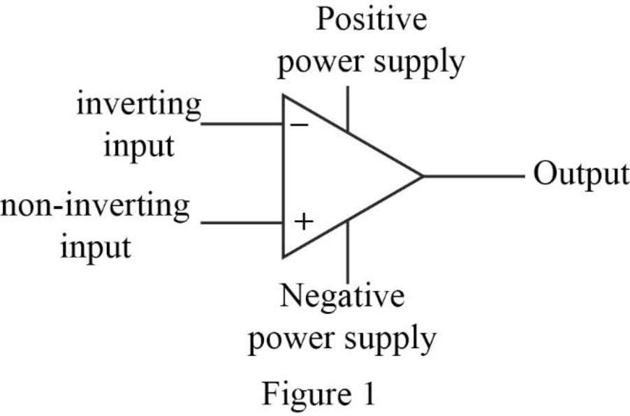
Label the five terminals in the operational amplifier.
a.
Explanation of Solution
Given data:
Refer to the given op amp circuit.
Discussion:
The five terminals of the op amp are labeled and it is shown in Figure 1.
Conclusion:
Thus, the five terminals in the operational amplifier are labeled.
b.
Mention the parameter that constraints the value of
b.
Answer to Problem 1P
The input resistance of the op amp constraints the value of
Explanation of Solution
Discussion:
The input resistance of an ideal op amp is infinite, which restricts the current
Conclusion:
Thus, the input resistance of the op amp constraints the value of
c.
Mention the parameter that constraints the value of
c.
Answer to Problem 1P
The open loop voltage gain of the op amp constraints the value of
Explanation of Solution
Discussion:
The open loop voltage gain of an ideal op amp is infinite, which constraints the difference between the voltage appear across the inverting and non-inverting terminal of the op amp to 0 V. Therefore,
Conclusion:
Thus, the open loop voltage gain of the op amp constraints the value of
d.
Find the value of voltage
d.
Answer to Problem 1P
The value of voltage
Explanation of Solution
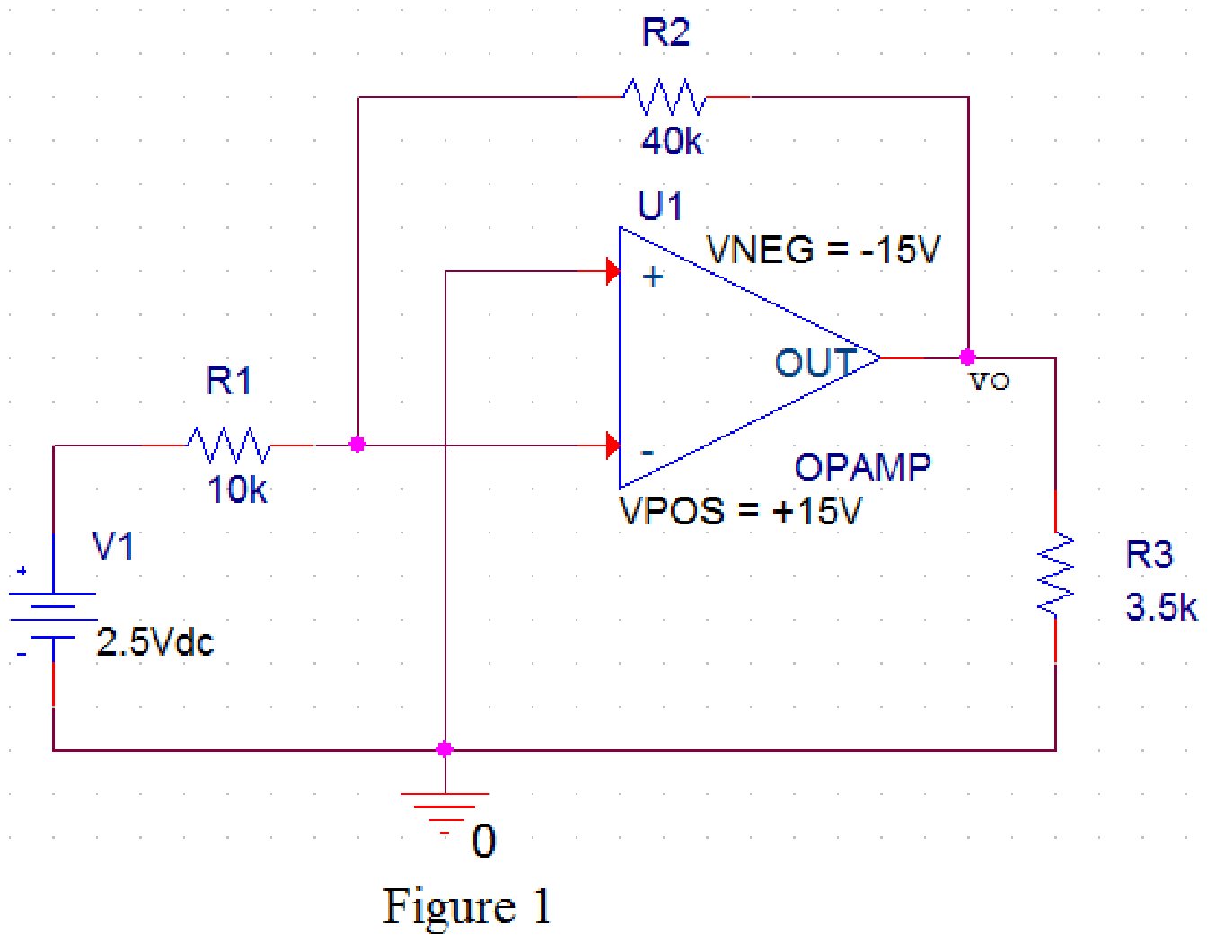
PSpice design:
Draw the given circuit in PSPICE as shown in Figure 2.
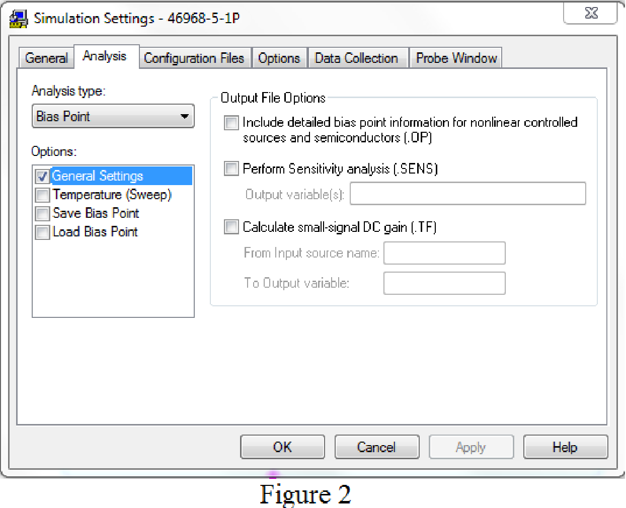
Provide the simulation settings as shown in Figure 3 to obtain output parameters.
After simulating the PSPICE circuit, the output voltage
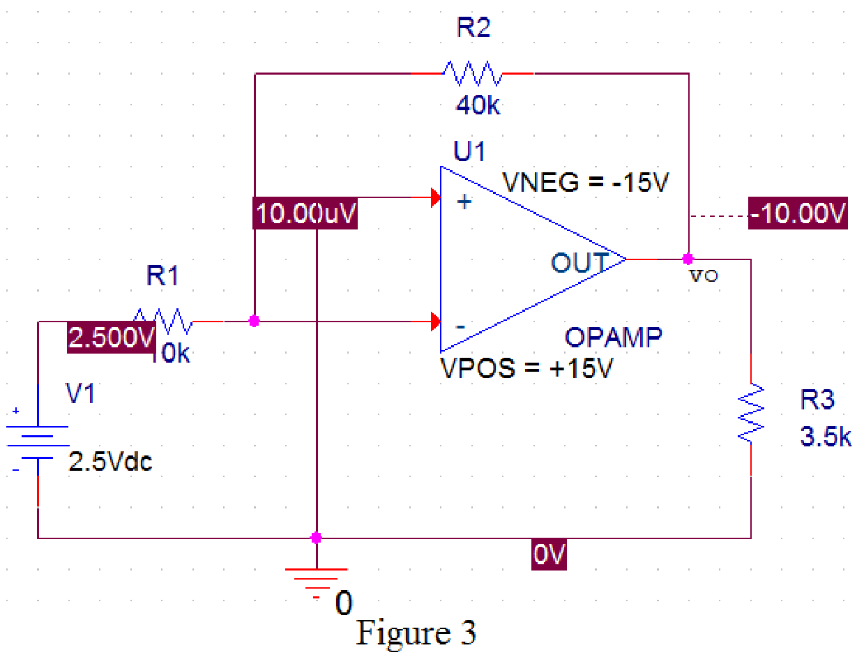
From Figure 4, the output voltage
Conclusion:
Thus, the value of voltage
Want to see more full solutions like this?
Chapter 5 Solutions
Electric Circuits. (11th Edition)
Additional Engineering Textbook Solutions
Electrical Engineering: Principles & Applications (7th Edition)
Electric Circuits (10th Edition)
Fundamentals of Applied Electromagnetics (7th Edition)
Introductory Circuit Analysis (13th Edition)
Mechanics of Materials
Engineering Mechanics: Statics & Dynamics (14th Edition)


 Introductory Circuit Analysis (13th Edition)Electrical EngineeringISBN:9780133923605Author:Robert L. BoylestadPublisher:PEARSON
 Delmar's Standard Textbook Of ElectricityElectrical EngineeringISBN:9781337900348Author:Stephen L. HermanPublisher:Cengage Learning
 Programmable Logic ControllersElectrical EngineeringISBN:9780073373843Author:Frank D. PetruzellaPublisher:McGraw-Hill Education
 Fundamentals of Electric CircuitsElectrical EngineeringISBN:9780078028229Author:Charles K Alexander, Matthew SadikuPublisher:McGraw-Hill Education
 Electric Circuits. (11th Edition)Electrical EngineeringISBN:9780134746968Author:James W. Nilsson, Susan RiedelPublisher:PEARSON
 Engineering ElectromagneticsElectrical EngineeringISBN:9780078028151Author:Hayt, William H. (william Hart), Jr, BUCK, John A.Publisher:Mcgraw-hill Education,