
Concept explainers
Videos
For each configuration in Fig. 5.88, find the individual (not combinations of) elements (voltage sources and/or resistors) that are in series.
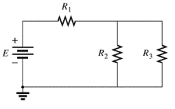
(a)
The individual elements that are connected in series for the given configuration.
Answer to Problem 1P
The individual elements that are connected in series for the given configuration are
Explanation of Solution
Given:
The circuit is given below.
Calculation:
The given circuit is analyzed by the rules of series-parallel combination.
As per the series combination rule,
Conclusion:
(b)
The individual elements that are connected in series for the given configuration.
Answer to Problem 1P
The individual elements that are connected in series for the given configuration are
Explanation of Solution
Given:
The circuit is given below,
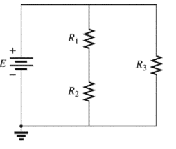
Calculation:
The given circuit is analyzed by the rules of series-parallel combination.
As per the series combination rule,
Conclusion:
(c)
The individual elements that are connected in series for the given configuration.
Answer to Problem 1P
The individual elements that are connected in series for the given configuration are
Explanation of Solution
Given:
The circuit is given below,
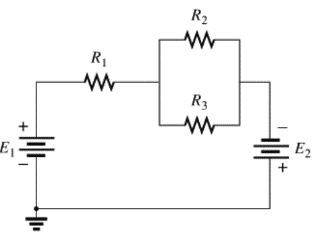
Calculation:
The given circuit is analyzed by the rules of series-parallel combination.
As per the series combination rule,
Conclusion:
(d)
The individual elements that are connected in series for the given configuration.
Answer to Problem 1P
The individual elements that are connected in series for the given configuration are
Explanation of Solution
Given:
The circuit is given below,
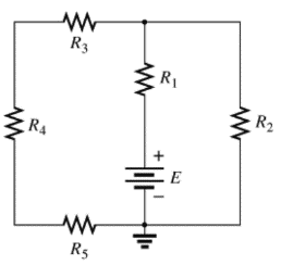
Calculation:
The given circuit is analyzed by the rules of series-parallel combination.As per the series combination rule of resistances,
Conclusion:
Therefore,
Want to see more full solutions like this?
Chapter 5 Solutions
EBK INTRODUCTORY CIRCUIT ANALYSIS
Additional Engineering Textbook Solutions
Fundamentals of Applied Electromagnetics (7th Edition)
Electrical Engineering: Principles & Applications (7th Edition)
Modern Database Management
Foundation Design: Principles and Practices (3rd Edition)
Web Development and Design Foundations with HTML5 (8th Edition)
C++ How to Program (10th Edition)


- Can you please show the solution of the image below. Thanks!arrow_forwardThe relationship between voltage and current is the same for two opposite directions of current in case ofchoose below bilateral network active network unilateral network passive networkarrow_forwardPerform a general analysis of the zener network.arrow_forward
- Answer the following and show complete solutions. View Image.arrow_forwardMetal interconnect lines in Ie circuits form parasitic MOS capacitors as illustrated in Fig. 5-37. Generally. one wants to prevent the underlying Si substrate from becoming inverted. Otherwise, parasitic transistors may be formed and create undesirable current paths between the N+ diffusions.arrow_forwardRefer to Table 5 – 1 and Fig. 5 – 4. According to Kirchhoff’s Voltage Law, what is the sum of all voltages in the circuit?a. +21 Vdcb. 42 Vdcc. Zerod. – 21 Vdcarrow_forward
 Introductory Circuit Analysis (13th Edition)Electrical EngineeringISBN:9780133923605Author:Robert L. BoylestadPublisher:PEARSON
 Delmar's Standard Textbook Of ElectricityElectrical EngineeringISBN:9781337900348Author:Stephen L. HermanPublisher:Cengage Learning
 Programmable Logic ControllersElectrical EngineeringISBN:9780073373843Author:Frank D. PetruzellaPublisher:McGraw-Hill Education
 Fundamentals of Electric CircuitsElectrical EngineeringISBN:9780078028229Author:Charles K Alexander, Matthew SadikuPublisher:McGraw-Hill Education
 Electric Circuits. (11th Edition)Electrical EngineeringISBN:9780134746968Author:James W. Nilsson, Susan RiedelPublisher:PEARSON
 Engineering ElectromagneticsElectrical EngineeringISBN:9780078028151Author:Hayt, William H. (william Hart), Jr, BUCK, John A.Publisher:Mcgraw-hill Education,